Scanning device, scanning method thereof, and laser radar

The technology of a scanning device and a scanning method, which is applied in the field of laser detection, can solve the problem of low scanning frequency and achieve the effects of increasing scanning frequency, shortening the time of single detection, high scanning frequency and high coherence efficiency

Active Publication Date: 2019-03-08
HESAI TECH CO LTD
View PDF23 Cites 7 Cited by
  • Summary
  • Abstract
  • Description
  • Claims
  • Application Information

AI Technical Summary

Problems solved by technology

Therefore, in order to improve the coherence efficiency between the local oscillator light and the echo light to ensure the signal-to-noise ratio of the coherent signal, angle compensation must be performed to suppress the decrease in coherence efficiency caused by the delay angle.
[0005] However, in the prior art, lidar systems that can achieve angle compensation often have the problem of low scanning frequency

Method used


Image

  • Scanning device, scanning method thereof, and laser radar
  • Scanning device, scanning method thereof, and laser radar
  • Scanning device, scanning method thereof, and laser radar

Examples


Embodiment Construction

[0038] It can be seen from the background art that the laser radar system capable of realizing angle compensation in the prior art has the problem of too low scanning frequency. Now combine the method of angle compensation of the laser radar system to analyze the reasons for the low scanning frequency:

[0039] At present, in lidar, the method of suppressing the delay angle is mainly divided into two categories: step scanning and local angle compensation. Wherein, the step scanning refers to the use of a non-continuous scanning mode, and the scanning device remains unchanged during a single detection until the next detection. Specifically, the existing laser radar realizes scanning by means of electro-optical devices such as stepping motors or liquid crystal optical waveguides.

[0040] Local angle compensation refers to the use of another reflection device to adjust the direction of the local oscillator light in real time while the scanning device is scanning, so as to ensur...


PUM


Abstract

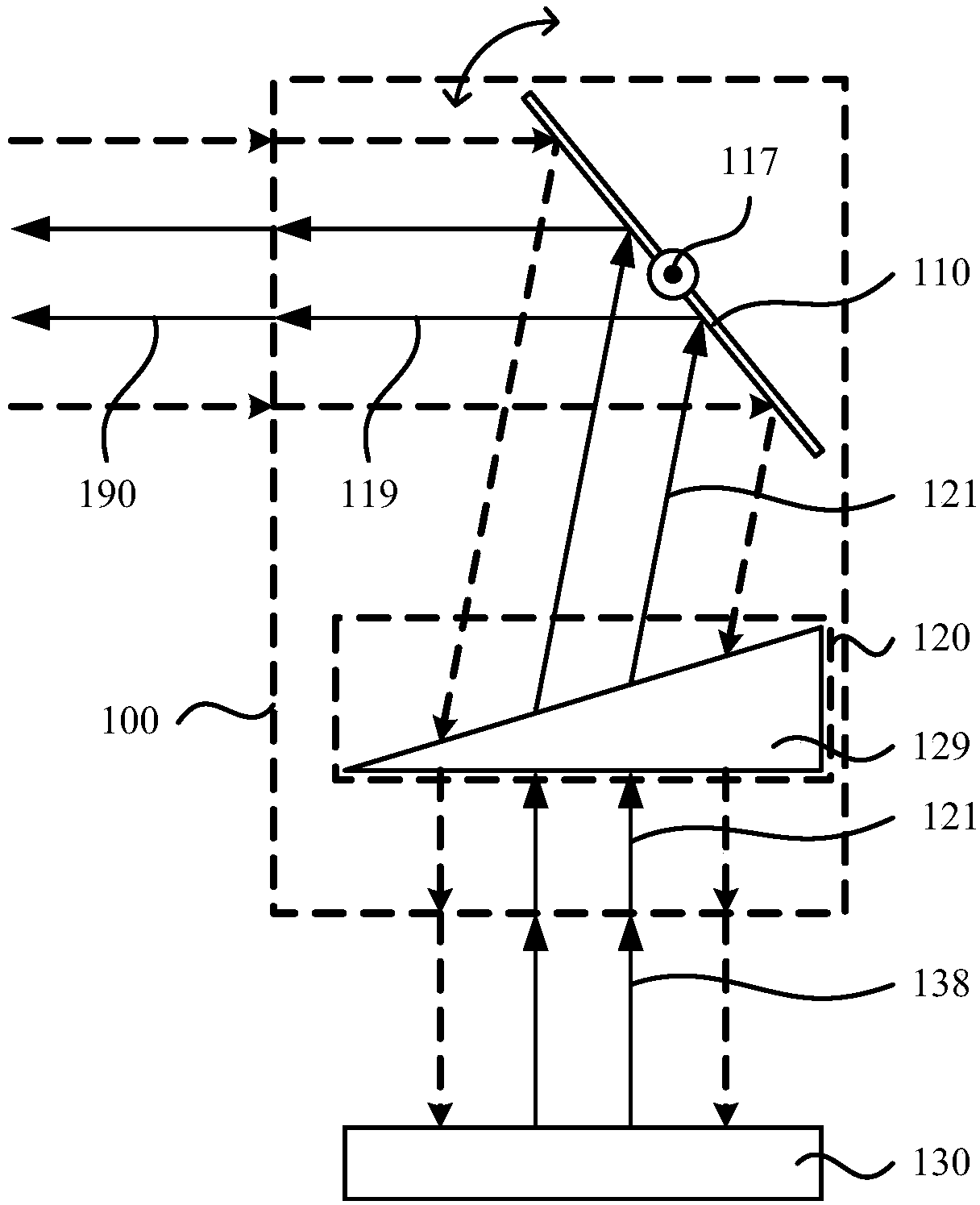
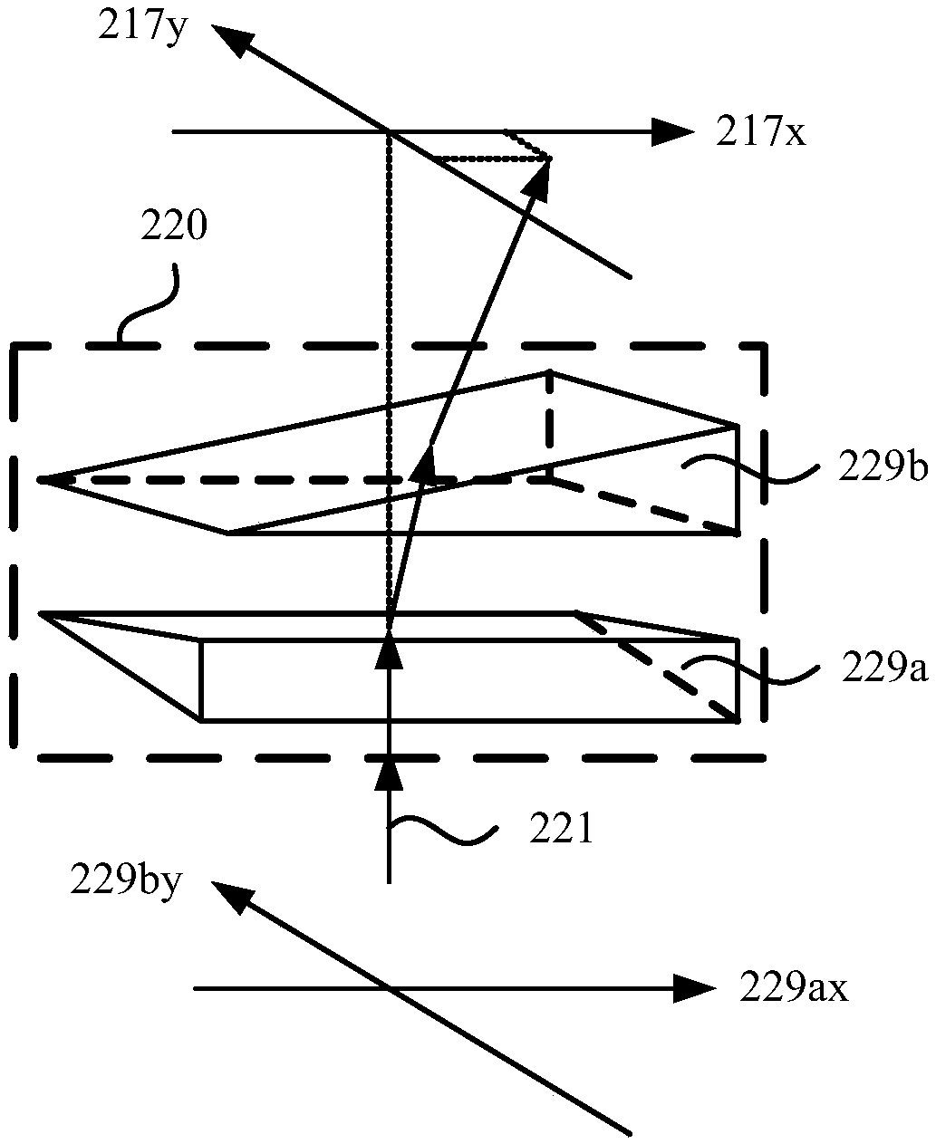
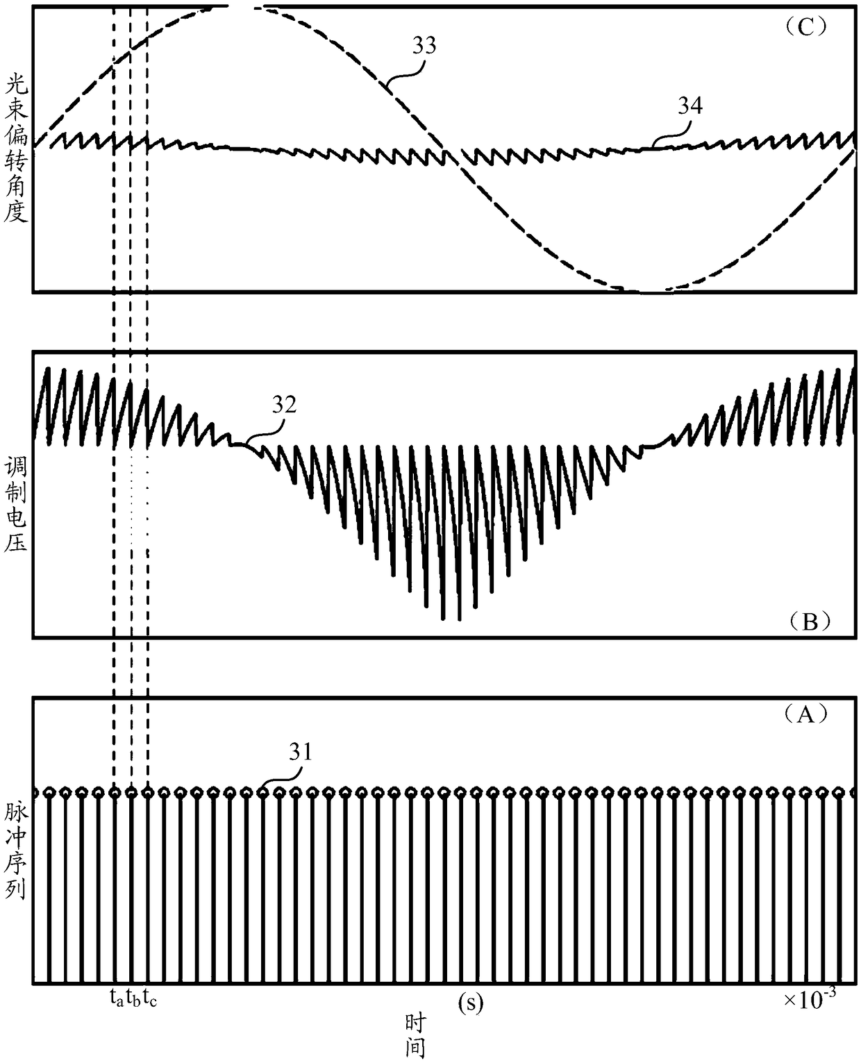
The invention relates to a scanning device, a scanning method thereof, and a laser radar. The scanning device comprises a first scanning unit and a second scanning unit; the first scanning unit is suitable for making the transmission direction of an incident light beam undergo first reflection so that the incident light beam can form an outgoing light beam; the first scanning unit changes the deflection angle of the first deflection by means of rotating or swinging; the second scanning unit is located in the optical path of at least one of the incident light beam and the outgoing light beam; and when the incident light beam or the outgoing light beam is transmitted through the second scanning unit, the second scanning unit makes the propagation direction of the transmitted light beam undergo second propagation based on an electro-optical effect. The scanning device can not only realize delay angle compensation, but also effectively shorten time for single detection, effectively improvescanning frequency, and is conductive to realizing the balance between high scanning frequency and high coherence efficiency.

Description

technical field [0001] The invention relates to the field of laser detection, in particular to a scanning device, a scanning method thereof, and a laser radar. Background technique [0002] Lidar is a commonly used ranging sensor, which has the characteristics of long detection distance, high resolution, and low environmental interference. It is widely used in intelligent robots, drones, unmanned driving and other fields. In recent years, with the rapid development of autonomous driving technology, lidar, as the core sensor of distance perception, has become indispensable. [0003] At present, most laser radars realize the scanning of the outgoing beam by continuous rotation or swinging back and forth. In a laser radar with a common channel for sending and receiving, the scanning device not only needs to realize the scanning of the outgoing beam, but also needs to realize the collection of the echo beam formed by the reflection of the target to be detected. Due to the cont...

Claims


Application Information

Patent Timeline
Patent Type & Authority Applications(China)
IPC IPC(8): G01S7/481
CPCG01S7/4817
Inventor 汪洋向少卿
Owner HESAI TECH CO LTD
Why Eureka
Try Eureka