Method for manufacturing inorganic fireproof medium-high voltage cable

A technology of medium and high voltage cables and manufacturing methods, which is applied in the manufacture of cables/conductors, for reducing the size of conductors/cables, insulating cables, etc., and can solve the problems of multiple cable laying, energy consumption, consumables, etc., and improve structural stability Performance and impact resistance, reducing stress and mechanical damage, and ensuring integrity

Active Publication Date: 2019-03-08
SICHUAN MINGXING CABLE
View PDF6 Cites 10 Cited by
  • Summary
  • Abstract
  • Description
  • Claims
  • Application Information

AI Technical Summary

Problems solved by technology

[0004] At present, most of the voltage levels of fire-resistant power cable products are concentrated at 1kV or below. However, if some super-large high-rise buildings and large-scale national key projects adopt 0.6/1kV low-voltage power distribution according to the usual practice, the amount of cable...

Method used


Image

  • Method for manufacturing inorganic fireproof medium-high voltage cable

Examples


Embodiment 1

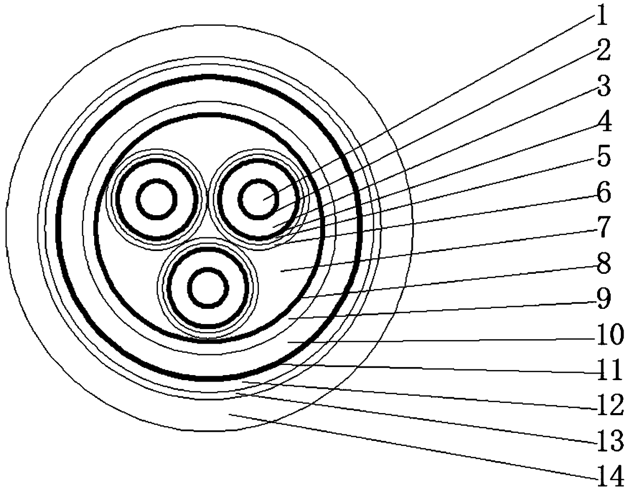
[0033]A method for manufacturing an inorganic fireproof medium and high voltage cable, the method comprising the following steps: A, wire drawing; B, conductor stranding; C, three-layer co-extrusion chemical crosslinking; D, wrapping buffer layer 5; Phase metal shielding layer 6; F, cabling; G, extruded oxygen barrier layer 9; H, inorganic fireproof layer 10 wrapped; I, metal armor; J, wrapped; K, extruded outer sheath 14; L , performance testing;

[0034] The wire-drawing step refers to the use of high-conductivity copper rods for electrical use on the wire-drawing annealing equipment to draw electrical round copper wires with different wire diameters through multiple molds;

[0035] The conductor stranding step refers to that the electrical round copper wire formed after the wire drawing process is twisted and compacted into a circular conductor 1 according to a stranding pitch that is 12 times the diameter of the stranding conductor;

[0036] The three-layer co-extrusion c...

Embodiment 2

[0047] A method for manufacturing an inorganic fireproof medium and high voltage cable, the method comprising the following steps: A, wire drawing; B, conductor stranding; C, three-layer co-extrusion chemical crosslinking; D, wrapping buffer layer 5; Phase metal shielding layer 6; F, cabling; G, extruded oxygen barrier layer 9; H, inorganic fireproof layer 10 wrapped; I, metal armor; J, wrapped; K, extruded outer sheath 14; L , performance testing;

[0048] The wire-drawing step refers to the use of high-conductivity copper rods for electrical use on the wire-drawing annealing equipment to draw electrical round copper wires with different wire diameters through multiple molds;

[0049] The conductor stranding step refers to that the electrical round copper wire formed after the wire drawing process is twisted and compacted into a circular conductor 1 according to a stranding pitch that is 12 times the diameter of the stranding conductor;

[0050] The three-layer co-extrusion ...


PUM

PropertyMeasurementUnit
Thicknessaaaaaaaaaa
Diameteraaaaaaaaaa
Melting pointaaaaaaaaaa

Abstract

The present invention discloses a method for manufacturing an inorganic fireproof medium-high voltage cable. The method comprises the following steps: A, performing wire drawing; B, performing conductor stranding; C, performing three-layer co-extrusion chemical crosslinking; D, wrapping a buffer layer; E, performing wrapping and phase separation on a metal shielding layer; F, performing cabling; G, extruding an oxygen barrier layer; H, performing inorganic fireproof layer wrapping; I, performing metal mounting; J, performing wrapping; K, extruding the outer sheath; and L, performing performance detection. According to the method provided by the present invention, the relationship between the electrical properties and the fire fireproof performance of the medium-high voltage cable is fullyconsidered, the balance between the two is solved, and instead of the traditional wrapped or extruded ceramized silicone rubber, the grouting inorganic fireproof layer is taken as the heat insulationlayer, so that the fireproof characteristics of the cable are greatly improved; and the medium-high voltage cable manufactured by using the method is laid on the building and has strong fireproof performance, so that the damage to the power system caused by sudden fires and the like can be greatly delayed.

Description

technical field [0001] The invention relates to the technical field of cables, in particular to a method for manufacturing inorganic fireproof medium and high voltage cables. Background technique [0002] In today's society, the economy continues to grow, science and technology continue to advance, and the cable industry, which is the link of information and energy transmission, has developed rapidly. With the sharp increase in the demand for cables, the safety of their use has also received widespread attention. However, the sheath and insulation in the cable construction are generally made of plastic and rubber materials. The so-called places where cables are densely laid can easily cause fires. The dense laying of wires and cables is mainly concentrated in densely populated places such as high-rise buildings, subways, large entertainment venues, etc., and large national key projects such as nuclear power plants, petrochemicals, tunnels, airports, post and telecommunicati...

Claims


Application Information

Patent Timeline
IPC IPC(8): H01B13/00H01B13/02H01B13/14H01B13/22H01B13/24H01B13/26H01B9/02H01B7/18H01B7/29H01B7/295
CPCH01B7/18H01B7/29H01B7/292H01B7/295H01B9/025H01B9/027H01B13/0006H01B13/02H01B13/14H01B13/221H01B13/24H01B13/26
Inventor 黄静李广胜刘小兵盛业武陈光高沈智飞靳荐宇毛开裕
Owner SICHUAN MINGXING CABLE
Why Eureka
Try Eureka