
Grinding wheel dressing device and method for electrical discharge grinding

A technology for grinding processing and dressing devices, which is applied to the parts of grinding machine tools, abrasive surface adjustment devices, metal processing equipment, etc. It can solve the problems of frequent disassembly and replacement of grinding wheels, shorten the waiting time for downtime, facilitate cleaning, and reduce labor costs. The effect of intensity

Inactive Publication Date: 2019-03-12
AECC AVIATION POWER CO LTD
View PDF9 Cites 0 Cited by
  • Summary
  • Abstract
  • Description
  • Claims
  • Application Information

AI Technical Summary

Problems solved by technology

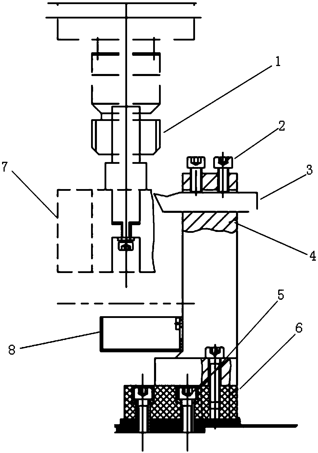
[0003] The object of the present invention is to provide a grinding wheel dressing device and grinding wheel dressing method for electric spark grinding, which solves the problem of frequent disassembly and replacement of grinding wheels when switching between rough, medium and finish machining processes

Method used

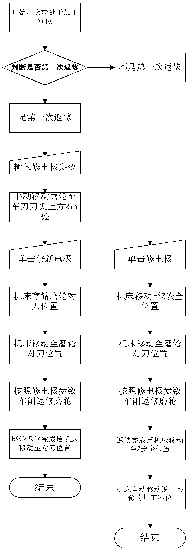
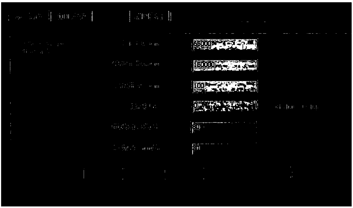

Image

  • Grinding wheel dressing device and method for electrical discharge grinding
  • Grinding wheel dressing device and method for electrical discharge grinding
  • Grinding wheel dressing device and method for electrical discharge grinding

Examples


Embodiment 1

[0048] Such as Figure 5 As shown, the X-axis moving part 11 , the Y-axis moving part 12 and the Z-axis moving part 10 are driven by a screw to finally realize the movement of the main shaft 1 in the three-coordinate system.

[0049] The programmable controller PLC is connected with the servo motor, X-axis motor, Y-axis motor and Z-axis motor; the servo motor is used to control the rotation of the main shaft 1, the X-axis motor is used to control the X-direction displacement of the main shaft 1, and the Y-axis motor is used for Control the Y-direction displacement of the spindle 1, and the Z-axis motor is used to control the Z-direction displacement of the spindle 1;

[0050] The X-axis moving part 11 includes an X-axis moving platform, and the X-axis moving platform is provided with an X-axis guide rail 111, an X-axis screw 112 and an X-axis slider 113, and the X-axis screw 112 is installed above the X-axis guide rail 111, and the X-axis The slider 113 is installed on the X-...

Embodiment 2

[0055] The transmission between the X-axis moving part 11 , the Y-axis moving part 12 and the Z-axis moving part 10 is realized through a guide rail pulley mechanism, and finally the movement of the main shaft 1 in the three-coordinate system is realized. Can refer to Figure 5 ,Will Figure 5 Sliders in are replaced with pulleys.

[0056] The programmable controller PLC is connected with the servo motor, Y-axis motor, Z-axis motor and stepping motor; the servo motor is used to control the rotation of the main shaft 1, the Y-axis motor is used to control the X-direction displacement of the main shaft 1, and the Z-axis motor is used for Control the Y-direction displacement of spindle 1, and the stepper motor is used to control the Z-direction displacement of spindle 1;

[0057] The X-axis moving part 11 includes an X-axis moving platform, and an X-axis guide rail 111 is arranged on the X-axis moving platform;

[0058] The Y-axis moving part 12 includes a Y-axis moving platfo...


PUM


Abstract

The invention belongs to the field of auxiliary equipment of electrical discharge grinding machine tools, and particularly discloses a grinding wheel dressing device and method for electrical discharge grinding. The grinding wheel dressing device comprises a grinding wheel mounting mechanism and dressing equipment for dressing a grinding wheel; the dressing equipment is arranged on one side of thegrinding wheel mounting mechanism; the grinding wheel mounting mechanism comprises a control system, a manual mechanism and a main shaft, and the control system and the manual mechanism are used forcontrolling the main shaft to rotate and move in a three-coordinate system; the grinding wheel is installed at the front end of the main shaft; the dressing equipment comprises a tool holder which isprovided with a tool carrier, and the tool carrier is internally provided with a turning tool used for dressing the grinding wheel; and the tool holder is fixedly installed on the base. The main shaftis controlled to move in the three-coordinate system and rotate through the control system and the manual mechanism, so that the grinding wheel is dressed by the turning tool located on one side automatically; the downtime of the equipment can be shortened effectively, and manual replacement of the grinding wheel is not required; and the labor intensity of workers is reduced.

Description

technical field [0001] The invention belongs to the field of electric spark grinding machine tool auxiliary equipment, and in particular relates to a grinding wheel dressing device and a grinding wheel dressing method for electric spark grinding. Background technique [0002] The turning tool of EDM usually adopts a cylindrical grinding wheel with a diameter of Φ100mm and a height of 50mm. Its movement mode is the same as that of conventional mechanical grinding, and its processing principle adopts the principle of EDM for material erosion. Since the workpiece and the grinding wheel will be worn out at the same time in the spark discharge, the grinding wheel needs to be disassembled and replaced frequently during rough, medium and finish machining, which increases the labor intensity of workers and the waiting time of equipment downtime. Contents of the invention [0003] The object of the present invention is to provide a grinding wheel dressing device and grinding wheel ...

Claims


Application Information

Patent Timeline
IPC IPC(8): B24B53/06
CPCB24B53/06
Inventor 陈阳王焕琴徐佩朱红钢李亚雷锋王亚东曹妮妮
Owner AECC AVIATION POWER CO LTD
Learn More