Visible light communication system based on spatial synthesis modulation and implementation method

A technology for visible light communication and space synthesis, applied in the field of visible light communication, can solve the problems of limited communication bandwidth of white LED lamps for general lighting, increase hardware cost and system complexity, and be unsuitable for ordinary indoor lighting systems, etc. The effect of low cost and high transmission rate

Active Publication Date: 2019-03-12
SICHUAN UNIV
View PDF5 Cites 6 Cited by
  • Summary
  • Abstract
  • Description
  • Claims
  • Application Information

AI Technical Summary

Problems solved by technology

Most of the existing technical solutions use dedicated blue light LEDs, complex codec algorithms and complex and expensive LED driver front-ends to achieve a suitable communication rate
However, the existing solutions are difficult to apply to low-cost lighting systems based on general lighting white LEDs, mainly for the following three reasons: 1) The communication bandwidth of general lighting white LED lights is limited. According to related research, the operating frequency of ordinary white LEDs ( That is, the bandwidth) is lower than 10MHz. If you want to increase the bandwidth, you must use an expensive blue lens that is not available in ordinary lighting systems; 2) Ordinary white LEDs have strong nonlinearity and require complex encoding and decoding algorithms, such as various pre-coding and equalization algorithm to achieve maximum optical power transmission, thus greatly incr

Method used


Image

  • Visible light communication system based on spatial synthesis modulation and implementation method
  • Visible light communication system based on spatial synthesis modulation and implementation method
  • Visible light communication system based on spatial synthesis modulation and implementation method

Examples


Embodiment Construction

[0027] The present invention will be further described below in conjunction with the accompanying drawings. It should be noted here that the descriptions of these embodiments are only used to help understanding of the present invention, and are not intended to limit the present invention.

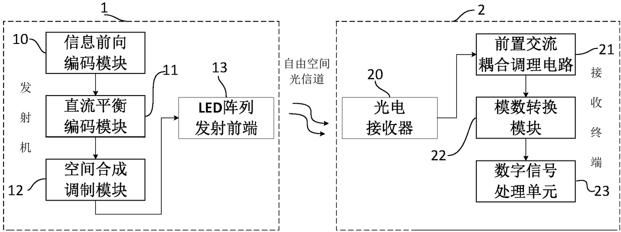
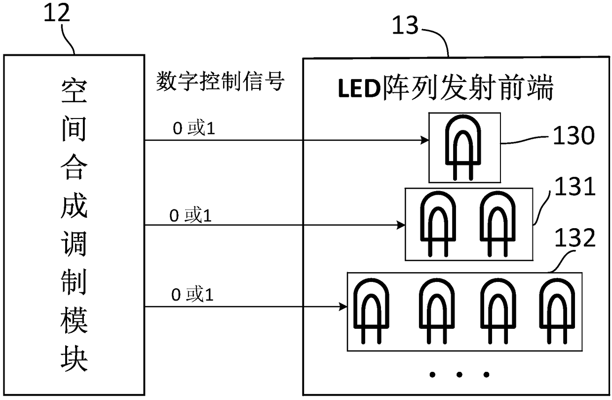
[0028] like Figure 1 to Figure 5 As shown, the visible light communication system based on spatial modulation of the present invention includes two parts: a transmitter 1 and a receiving terminal 2; the transmitter is mainly composed of an information forward encoding module 10, a DC balance encoding module 11, a spatial synthesis modulation module 12 and an LED array The transmitting front end 13 is composed, and the receiving terminal mainly includes a photoelectric receiver 20 , a pre-AC coupling conditioning circuit 21 , an analog-to-digital conversion template 22 and a digital signal processing unit 23 . The information forward encoding module 10 is used to encode information to be s...


PUM


Abstract

The invention discloses a visible light communication system based on spatial synthesis modulation and an implementation method. The system mainly comprises a transmitter and a receiving terminal, wherein the transmitter part comprises an information forward coding module, a direct current balance coding module, a spatial synthesis modulation module and an LED transmitting front end; the information forward coding module encodes input information by adopting a ratioless coding mode, and divides the information to generate coded data packets; the direct current balance coding module carries outsecondary coding on each data packet, so that the total power balance of each data packet is ensured, and lamplight flickering caused by data communication is avoided; and the spatial synthesis modulation module modulates the data packets to generate corresponding data symbols, and generates a digital control signal to control the LED transmitting module to send the information. The receiving terminal is used for receiving the information sent by a transmitting end and mainly comprises a photoelectric receiver, a front alternating current coupling conditioning circuit, an analog-digital conversion module and a digital signal processing unit.

Description

technical field [0001] The invention belongs to the technical field of visible light communication, and in particular relates to a visible light communication system based on space synthesis modulation technology and an implementation method thereof. The system uses general lighting LED lamps to realize high-speed wireless data communication services. Background technique [0002] With the development of society, people's demand for wireless data services has increased dramatically. On the one hand, the traditional communication system based on wireless radio frequency signals, such as WiFi, can no longer satisfy the data communication under high crowd density; on the other hand, the widespread use of LED-based indoor lighting Visible light communication system provides a good basis for deployment. Because visible light communication systems can reuse existing lighting setups while simultaneously achieving data communication and lighting functions. [0003] As one of the p...

Claims


Application Information

Patent Timeline
IPC IPC(8): H04B10/116H04B10/516
CPCH04B10/116H04B10/516
Inventor 杨彦兵罗骏陈晨陈良银陈硕王伟郭敏王浩
Owner SICHUAN UNIV
Why Eureka
Try Eureka