Device and method for treating waste water of power plant with flue gas

A technology for power plant waste water and furnace smoke, which is applied in special treatment targets, water/sewage treatment, chemical instruments and methods, etc., can solve the problems of high investment cost, large impact on unit efficiency, complex system, etc., and achieves low investment cost, The effect of improving continuous safe operation performance and system simplicity

Active Publication Date: 2019-03-15
XIAN THERMAL POWER RES INST CO LTD
View PDF6 Cites 4 Cited by
  • Summary
  • Abstract
  • Description
  • Claims
  • Application Information

AI Technical Summary

Problems solved by technology

Because the current conventional bypass flue gas evaporation technology needs to extract high-temperature flue gas, it has a great impact on the efficiency of t

Method used


Image

  • Device and method for treating waste water of power plant with flue gas
  • Device and method for treating waste water of power plant with flue gas

Examples


Embodiment 1

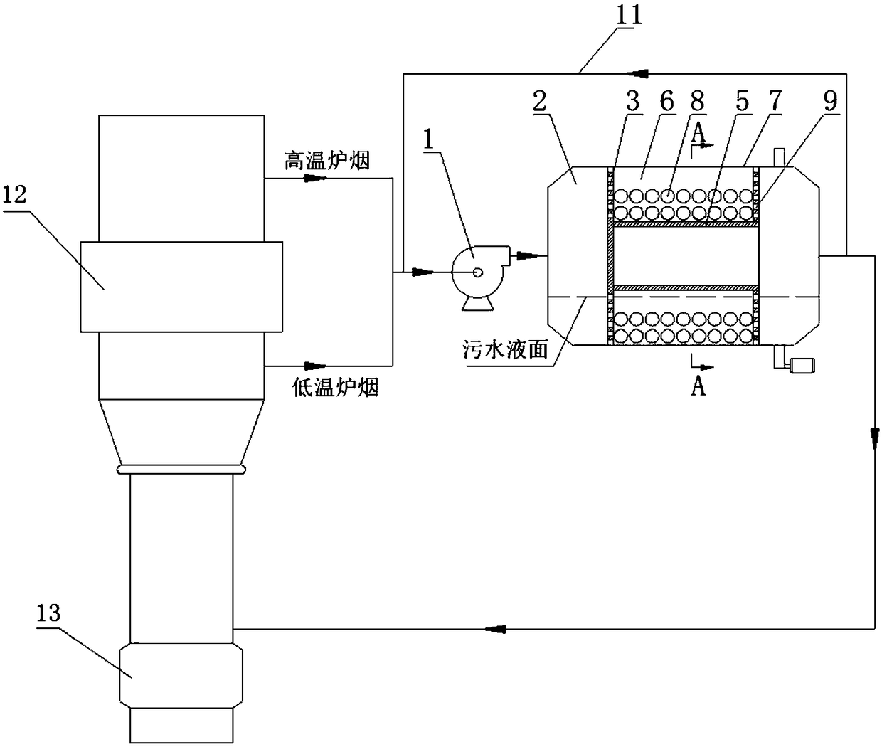
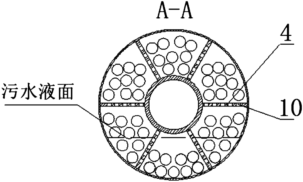
[0033] The present invention is a device for treating power plant waste water by using furnace smoke, such as figure 1 and figure 2 As shown, it includes a rotary wastewater treatment device 2, which includes a plurality of cavities 6 separated by a rotary device housing 7, a central cylinder 5, an axial partition 3, and a radial partition 4, and placed in the cavity 6 steel ball 8; the axial partition 3 is provided with a round hole 9 for the passage of a large amount of smoke and waste water; the radial partition 4 is provided with a round hole 10 for the passage of waste water, so that the waste water is always rotating The lower part of the processing device 2;

[0034] The high-temperature furnace smoke and the low-temperature furnace smoke are respectively taken at the inlet and outlet of the air preheater 12. After the high-temperature furnace smoke and the low-temperature furnace smoke are mixed, they enter the inlet of the furnace smoke fan 1, and the outlet of the ...

Embodiment 2

[0040] A method of utilizing furnace smoke to treat power plant waste water of the present invention comprises the following steps:

[0041] a. The high-temperature furnace smoke from the inlet flue of the air preheater 12 and the low-temperature furnace smoke from the outlet flue of the air preheater 12 in the flue are extracted by the furnace smoke fan 1, and the high-temperature furnace smoke and the low-temperature furnace smoke are mixed at the inlet of the furnace smoke fan 1 Send it into the rotary wastewater treatment device 2 to provide a heat source for the evaporation of sewage;

[0042] b. The mixed furnace smoke enters the rotary waste water treatment device 2 and enters the hollow body 6, and performs convective heat exchange on the steel ball 8 above the waste water liquid level at the lower part of the rotary waste water treatment device 2, and evaporates the sewage on the surface of the steel ball 8 to dryness. The steel balls 8 that have been evaporated to dr...


PUM


Abstract

The invention relates to the technical field of treatment of waste water of power plants and specifically relates to a device and method for treating waste water of a power plant with flue gas. The device comprises a rotary waste water treatment device, wherein the rotary waste water treatment device comprises a rotary device shell and a rotary driving device arranged outside the rotary device shell; the rotary device shell is in a hollow cylindrical shape, a flue gas inlet is formed in one end of the rotary device shell, a flue gas outlet is formed in the other end of the rotary device shell,and an annular cavity body is coaxially arranged inside the rotary device shell; the flue gas inlet is connected to an inlet flue of an air pre-heater and an outlet flue of the air pre-heater by fluegas fans respectively and is used for leading mixed flue gas of high temperature flue gas and low temperature gas; the flue gas outlet is connected to an inlet flue of a dust remover; the cavity bodyis divided into a plurality of cavities in the circumferential direction; a steel ball is arranged in each of the cavities; every two adjacent cavities communicate with each other; two ends of each of the cavities respectively communicate with the inside of the rotary device shell; and the waste water of the power plant is contained in the rotary device shell. The device provided by the inventionis small in energy consumption, low in operating cost, high in continuous and safe operating performance and wide in range of application.

Description

technical field [0001] The invention relates to the technical field of power plant wastewater treatment, in particular to a device and method for treating power plant wastewater by using furnace smoke. Background technique [0002] Large-scale coal-fired power plants are large industrial water consumers and wastewater dischargers. Reducing water consumption in coal-fired power plants and improving wastewater treatment and recycling levels are of great significance for coal-fired units to achieve energy conservation and environmental protection. As the country and society have higher and higher requirements for environmental protection, higher requirements are put forward for the operation of thermal power plants, and the wastewater of the whole plant must achieve zero discharge. The wastewater of large coal-fired power plants mainly includes: industrial wastewater, oily wastewater, chemical wastewater, coal transportation wastewater, desulfurization wastewater, slag system o...

Claims


Application Information

Patent Timeline
IPC IPC(8): C02F1/16
CPCC02F1/042C02F1/16C02F2303/14
Inventor 周虹光严万军吴庆龙王岩陈煜敬小磊房凡严响林白鹏
Owner XIAN THERMAL POWER RES INST CO LTD
Why Eureka
Try Eureka