Supercharge Your Innovation With Domain-Expert AI Agents!

Multi-stage condensation system for desulfurization flue gas

A flue gas condensation and condensation system technology, applied in steam condensation, multi-effect/separation condensation, gas treatment, etc., can solve the problems of limited cooling range, limited removal assistance, etc., to achieve extended contact time and area, low resistance , The effect of difficult water balance control

Pending Publication Date: 2019-03-19
GUODIAN ENVIRONMENTAL PROTECTION RES INST CO LTD
View PDF0 Cites 4 Cited by
  • Summary
  • Abstract
  • Description
  • Claims
  • Application Information

AI Technical Summary

Problems solved by technology

However, the greater the cooling range, the greater the impact on the desulfurization water balance, and the cooling range is limited
Moreover, this method has limited help in the removal of pollutants such as soluble salts.

Method used


Image

  • Multi-stage condensation system for desulfurization flue gas
  • Multi-stage condensation system for desulfurization flue gas
  • Multi-stage condensation system for desulfurization flue gas

Examples


Embodiment 1

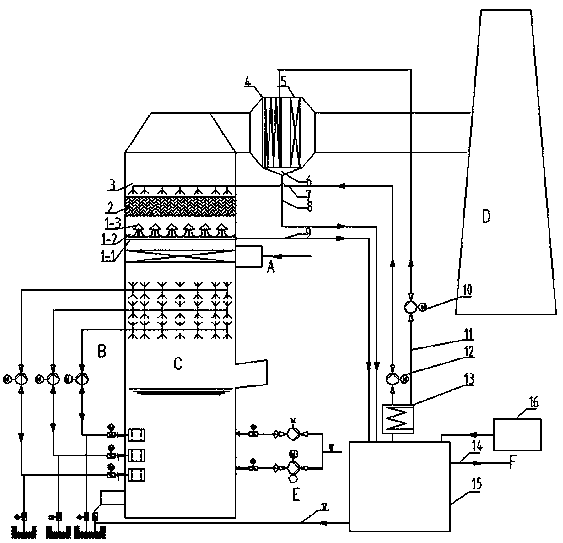
[0036] The desulfurization flue gas multi-stage condensation system of the present invention comprises three parts in sequence according to the flue gas flow direction: a spray flue gas cooling system arranged in the tower; a flue gas condensation phase change system connected to the flue; and a flue gas condensation phase change system arranged outside the tower The water circulation system, the flue gas condensing heat exchanger adopts the flue type flue gas condensing heat exchanger.

[0037] The flue gas spray cooling system is arranged above the demister in the desulfurization absorption tower, and includes, from bottom to top, water recovery device (1), water distribution layer (2) and spray device (3);

[0038] The flue gas condensation phase change system includes a flue gas condensation heat exchanger (4) and a demister (5) arranged according to the flue gas flow direction;

[0039] The water circulation system includes a circulating water cooling system (14), a water...

Embodiment 2

[0043]In this example, the further design is that the flue gas condensation phase change system also includes a liquid collection tank (6), the flue gas condensation heat exchanger (4) and the demister (5) are arranged front and back, and the liquid collection tank (6) is arranged in The bottom of the two is used to collect the condensed water effluent collected by the flue gas condensation heat exchanger (4) and the mist eliminator (5). The liquid collection tank (6) recovers the liquid droplets formed by condensation and the circulating cooling water, and enters the water tank (15) for reuse through the recovery water pipeline (8).

Embodiment 3

[0045] In this example, the further design is that the water distribution layer (2) adopts a layer of folded plate device, which can form a water distribution layer on the board and form a group of water films on both sides to expand the condensed water and smoke. The contact time and area are improved, and the efficiency of pollutant collection is improved at the same time. The flue gas passes through two layers of water film. Improve the removal efficiency of pollutants such as smoke and dust, and reduce the pressure on the dust removal equipment before desulfurization.


PUM


Abstract

The invention provides a multi-stage condensation system for desulfurization flue gas, which realizes pollutant removal with high efficiency. The multi-stage condensation system for the flue gas sequentially comprises a spraying flue gas cooling system disposed in a tower, a flue gas condensation phase change system connected to a flue, and a water circulation system disposed outside the tower according to a flue gas flow direction, wherein the spraying flue gas cooling system is disposed above a demister in a desulfurization absorption tower and sequentially comprises, from bottom to top, a water recycling device (1), a water distribution layer (2) and a spraying device (3); the flue gas condensation phase change system comprises a flue gas condensation heat exchanger (4) and the demister(5) which are disposed according to the flue gas flow direction; the water circulation system comprises a flue gas condensation heat exchanger (14), a water tank (16) and a water pump . The system has lower requirements on a site, less influence on the water balance of desulfurization water, high pollutant removal capability and higher cooling capability.

Description

technical field [0001] The invention relates to the technical field of wet smoke plume treatment in coal-fired power plants, and more specifically relates to a multi-stage condensation system for flue gas after desulfurization. Background technique [0002] At present, the treatment of wet smoke plume in coal-fired power plants has become the main transformation work in the next step. The current mainstream processes include flue gas condensation process and slurry cooling process. It can greatly reduce the pollutants and water vapor in the flue gas, and effectively reduce the phenomenon of wet plume (that is, "white smoke") in the chimney. [0003] The condensation process of the flue gas heat exchanger condenses and collects droplets, soluble salts, SO 3 , Hg and other pollutants, while using a high-efficiency demister to further remove particulate matter. However, in order to achieve a large cooling range in this process, a long flue is required, the heat exchange effi...

Claims


Application Information

Patent Timeline
IPC IPC(8): B01D50/00B01D53/18B01D5/00
CPCB01D5/0036B01D5/0057B01D50/00B01D53/18B01D2258/0283
Inventor 舒喜申智勇刘志坦杨爱勇韦飞孙尊强叶毅科王特李二欣张昕李瑾
Owner GUODIAN ENVIRONMENTAL PROTECTION RES INST CO LTD
Features
  • R&D
  • Intellectual Property
  • Life Sciences
  • Materials
  • Tech Scout
  • Unparalleled Data Quality
  • Higher Quality Content
  • 60% Fewer Hallucinations
Learn More