
Plate welding method

A plate and laser welding technology, applied in welding equipment, laser welding equipment, arc welding equipment, etc., can solve the problems of poor welding process stability, violent evaporation of materials, splashing bottom, etc., to achieve smoothness, improve process stability, Effect of Surface Tension Reduction

Active Publication Date: 2019-03-22
CHANGSHA UNIVERSITY OF SCIENCE AND TECHNOLOGY
View PDF8 Cites 2 Cited by
  • Summary
  • Abstract
  • Description
  • Claims
  • Application Information

AI Technical Summary

Problems solved by technology

[0004] The purpose of the present invention is to solve the problem that the current high-power optical fiber laser welding process is caused by the local violent evaporation of the material due to the small hole wall wrinkles, which further affects the poor stability of the welding process and is easy to form defects such as spatter and bottom root leakage.

Method used


Image

  • Plate welding method
  • Plate welding method
  • Plate welding method

Examples


Embodiment Construction

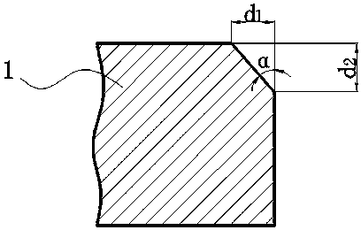
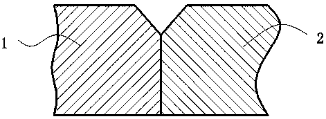
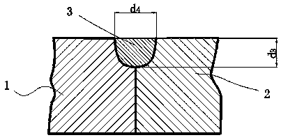
[0033] The following will be combined with the attached Figure 1-6 Specific embodiments of the present invention will be described in detail.

[0034] In this embodiment, a method for welding plates includes the following steps.

[0035] Step 1: Process the first base material 1 and the second base material 2 to form the butt end surface and the groove surface, and remove the impurities on the upper and lower surfaces of the first base material 1 and the second base material 2, the butt surface and the welding groove, these impurities Including water stains, oil stains, rust, etc.

[0036] Such as figure 1 As shown, the first base metal 1 and the second base metal 2 have the same groove surface structure and size, and the groove width d 1 1mm~2mm, groove height d 2 1.5mm~3mm.

[0037] Step 2: Use a special welding fixture to accurately butt and clamp the first base metal 1 and the second base metal 2 to achieve precise alignment of the welding grooves of the first base m...


PUM

PropertyMeasurementUnit
Widthaaaaaaaaaa
Heightaaaaaaaaaa

Abstract

The invention relates to a laser plate welding method. The method is characterized by comprising the following steps that S1, a first parent material and a second parent material are machined to formbutt-joint end surfaces and groove surfaces, and impurities on the upper surfaces, the lower surfaces, the butt-joint end surfaces and the groove surfaces of the first parent material and the second parent material are removed; S2, the first parent material and the second parent material are accurately connected and clamped in a butt-joint manner; S3, welding rods added with rare earth elements are provided; S4, a manual consumable-electrode metal-inert gas welding (MIG) method is adopted, and butt-joint grooves of the first parent material and the second parent material are welded; and S5, high-power optical fiber laser beams formed by laser welding head focusing irradiate on the surfaces of MIG welding seams, and then penetration welding of the first parent material and the second parentmaterial is achieved. According to the method, a welding seam layer which is rich in rare earth elements is loaded in the upper portion of small-hole welding plates, and the surface tension of the front wall of each small hole is effectively improved in the laser welding process, so that a smooth small hole wall form is obtained, the stability of the optical fiber laser welding process is improved, and the defects of splashing, root leakage and the like are avoided.

Description

technical field [0001] The invention relates to a welding method, in particular to a method for welding plates. Background technique [0002] Laser welding is one of the most widely used advanced processes in laser processing technology. It has the advantages of small welding heat input, large weld depth-to-width ratio, fast speed, small weld deformation and low residual stress, high welding precision and strength, large penetration depth, It has outstanding advantages such as easy realization of automation, and has been applied in important industries of the national economy such as automobiles, shipbuilding, nuclear power, and pipelines. [0003] Laser welded sheets are usually laser deep penetration welded. In this mode, the material is melted or even gasified under the direct irradiation of the high-energy-density laser, and the surface of the molten pool sinks under the action of evaporation pressure to form a "keyhole" (also called a small hole), and the laser beam pe...

Claims


Application Information

Patent Timeline
IPC IPC(8): B23K26/348B23K9/167B23K26/70
CPCB23K9/167B23K26/348B23K26/70
Inventor 刘子奇张明军戴家辉张远康
Owner CHANGSHA UNIVERSITY OF SCIENCE AND TECHNOLOGY
Learn More