Stress deformation control method and device for electron beam fuse additive manufacturing process

A technology of additive manufacturing and stress deformation, applied in the field of additive manufacturing, can solve the problems of weakening the integrity of parts, increasing cost and cycle, increasing process complexity, etc., and achieve the effect of reducing deformation tendency and thermal stress

Active Publication Date: 2019-03-26
AVIC BEIJING AERONAUTICAL MFG TECH RES INST
View PDF15 Cites 5 Cited by
  • Summary
  • Abstract
  • Description
  • Claims
  • Application Information

AI Technical Summary

Problems solved by technology

This method has been applied industrially and has a good effect of controlling deformation. The disadvantage is that it increases the complexity of the process, weakens the integrity of the parts, and increases the cost and cycle time.
3) Auxiliary rolling, impact, etc., the test effect is obvious, but additional equipment needs to be added, and the structure of the machine tool also needs special adjustments, which cannot solve the problems under the existing conditions
In actual work, multiple methods are often used to control the deformation trend of parts, but this will increase the complexity of the process, increase the cost and cycle time

Method used


Image

  • Stress deformation control method and device for electron beam fuse additive manufacturing process
  • Stress deformation control method and device for electron beam fuse additive manufacturing process

Examples


Embodiment Construction

[0032] Embodiments of the present invention will be further described in detail below in conjunction with the accompanying drawings and examples. The detailed description and accompanying drawings of the following embodiments are used to illustrate the principles of the present invention, but cannot be used to limit the scope of the present invention, that is, the present invention is not limited to the described embodiments, without departing from the spirit of the present invention Any modification, substitution and improvement of parts, components and connection methods are covered under.

[0033] It should be noted that, in the case of no conflict, the embodiments in the present application and the features in the embodiments can be combined with each other. The present application will be described in detail below with reference to the accompanying drawings and embodiments.

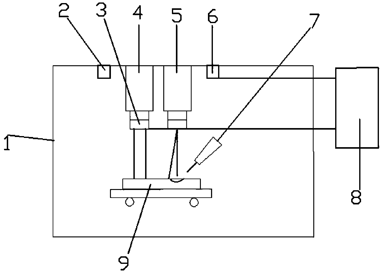
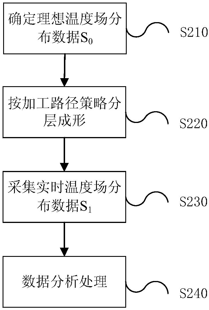
[0034] combine figure 1 with figure 2 As shown, the stress deformation control device of the ...


PUM


Abstract

The invention relates to a stress deformation control method and device for an electron beam fuse additive manufacturing process. The method comprises the steps that ideal temperature field distribution data S0 for generating minimum thermal stress during additive manufacturing is determined based on material properties and thermal stress generation conditions of additive manufacturing; a metal wire is melted with a first electron gun, and layered forming is performed according to a machining path strategy of a part; a temperature monitoring probe is used for collecting real-time temperature field distribution data S1 of a forming layer; the real-time temperature field distribution data S1 is compared with the ideal temperature field distribution data S0, and when it is judged that S1 deviates from S0, an electron beam is emitted by a second electron gun, after the electron beam is controlled by a scanning coil, the electron beam is irradiated in a spot mode at a position at which thepart to be heated is formed, and when the real-time temperature field distribution data S1 in the forming process is equivalent to the ideal temperature field distribution data S0, the second electrongun and the scanning coil stop working, the first electron gun continues to work until all the layers of the part are formed.

Description

technical field [0001] The invention relates to the technical field of additive manufacturing, in particular to a method and device for controlling stress deformation in an electron beam fuse additive manufacturing process. Background technique [0002] Electron beam fuse additive manufacturing technology refers to a direct energy deposition that uses electron beams to melt synchronously fed metal wires in a vacuum environment and accumulate them layer by layer according to a pre-planned path to directly manufacture the required parts or blanks. craft. Electron beam fuse additive manufacturing technology has the characteristics of fast forming speed and excellent internal quality, and is suitable for efficient and high-quality forming of large-scale high-performance metal components. [0003] One of the bottlenecks of electron beam fuse additive manufacturing technology in the manufacture of large metal components is stress and deformation control. At present, the main met...

Claims


Application Information

Patent Timeline
IPC IPC(8): B23K15/00
CPCB23K15/00B23K15/0026
Inventor 杨光杨帆董伟巩水利
Owner AVIC BEIJING AERONAUTICAL MFG TECH RES INST
Why Eureka
Try Eureka