Rapid preparation method and application of colloidal probe

A technology of probes and colloids, which is applied in the field of rapid preparation of colloidal probes, can solve problems such as unfavorable universal use, limited application range, and easy to pollute the surface of samples, so as to reduce the probability of pollution or damage, expand the scope of application and research, The effect of improving the success rate of preparation

Pending Publication Date: 2019-03-26
TIANJIN UNIV
View PDF6 Cites 7 Cited by
  • Summary
  • Abstract
  • Description
  • Claims
  • Application Information

AI Technical Summary

Problems solved by technology

The traditional two-wire method requires two very thin metal wires for the movement and positioning of colloidal particles and particle bonding, which has the disadvantages of cumbersome procedures, easy contamination of the sample surface and damage to the probe, and low efficiency and success rate.
Although the microtube cantilever suction method is accurate and fast, the technology is still immature and the probes are expensive, which is not conducive to widespread use
At present, the most commonly ...

Method used


Image

  • Rapid preparation method and application of colloidal probe
  • Rapid preparation method and application of colloidal probe
  • Rapid preparation method and application of colloidal probe

Examples


Embodiment 1

[0058] 1. Substrate material cleaning. Place a piece of 18*18*2mm glass piece in ultrapure water, acetone, and ultrapure water in sequence, ultrasonically clean it for 10 minutes respectively to fully remove surface pollutants, and then dry it for later use to obtain glass piece G.

[0059] 2. Colloid solution dilution. Set the concentration to 4.99 x 10 8 particles / ml, the stock solution A of polystyrene beads with a particle size of 4.5um was diluted with ultrapure water to obtain a concentration of 2.50×10 6 particles / ml of dispersion B.

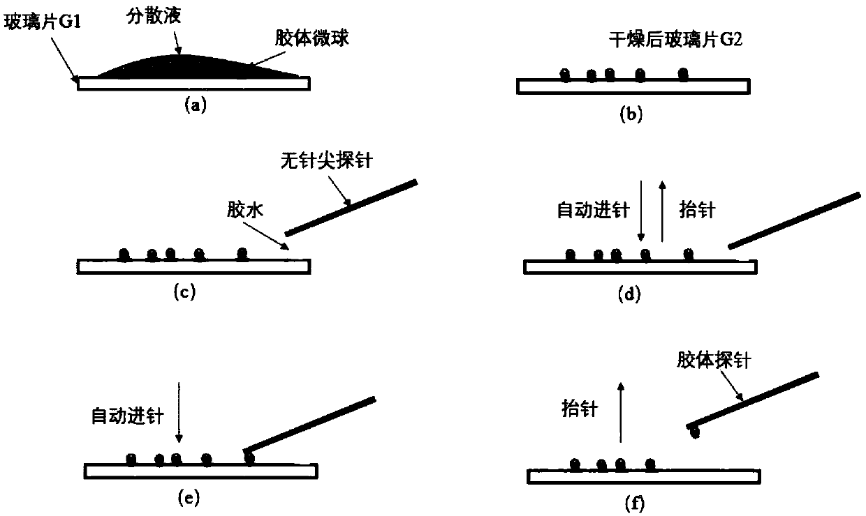
[0060] 3. Dispersion of colloidal spheres. Use a pipette to take 20uL of dispersion B and drop it on one side of the cleaned glass slide G1, such as figure 1 Shown in (a).

[0061] 4. The dispersion is dried. On the heating plate, under the condition of 40°C, properly heat the glass sheet to accelerate the volatilization of the dispersion liquid, dry the microspheres, and obtain the glass sheet G2 uniformly covered with microspheres...

Embodiment 2

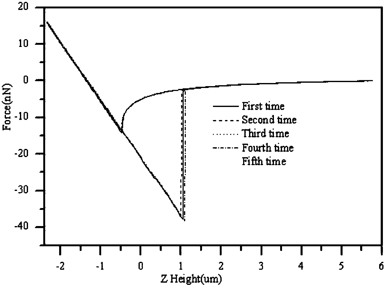
[0069] According to the TL-COUNT probe prepared in Example 1, the non-contact force between the colloidal microsphere and the glass plate was studied, and the F-D curve was tested by using the Contact mode of ParkNX10AFM. The specific steps are as follows:

[0070] 1. AFM parameter calibration. Install the newly prepared colloidal probe, and adjust the AFM calibration probe parameters, including "Sensitivity", "Force slope" and "Force constant". After calibration, the "Sensitivity" and "Force constant" are 4.1V / um and 10 -3 (N / m).

[0071] 2. Test base preparation. A 15*15mm clean glass sheet with a roughness less than 100nm was selected as the base, the needle feeding / lifting speed was set to 1.0um / s, and the experiment was carried out at room temperature. For the detailed experimental process, please refer to [Assemi S, Nalaskowski J, Johnson W P. Direct force measurements between carboxylate-modified latexmicrospheres and glass using atomic force microscopy[J].Colloids a...


PUM

PropertyMeasurementUnit
Particle sizeaaaaaaaaaa
Roughnessaaaaaaaaaa

Abstract

The invention discloses a rapid preparation method and application of a colloidal probe. The method comprises the steps of material cleaning, colloidal ball dispersion, glue line preparation, probe glue coating and colloidal probe preparation. The colloidal probe is used for researching the non-contact force relationship between a colloidal microsphere and a glass plate to acquire the F-D curve ofthe colloidal probe and the glass plate in air. According to the invention, AFM equipped with a forward/inverted optical imaging system is used; a three-axis motion controller of AFM is combined to realize glue coating of the probe and accurate positioning and bonding of mesoscopic particles and the probe; and efficient and quick colloidal probe preparation is realized.

Description

technical field [0001] The invention relates to the fields of precision instruments and colloid science, and more specifically, relates to a rapid preparation method and application of a colloid probe. Background technique [0002] Atomic Force Microscope (AFM) was invented in 1986 by Gerd Binning and Heinrich Rohrer, two scientists of IBM Laboratory. They created a new way of observation, so that people can observe the surface of the sample and the near-surface area more deeply. The physical properties such as morphology, electricity, and mechanics provide atomic-level resolution [Binnig G, Quate C F, Gerber C. Atomic force microscope [J]. Physical review letters, 1986, 56 (9): 930.]. The probe of an atomic force microscope generally consists of a tip, a microcantilever and a matrix. The needle tip is a key part of the probe, which directly determines the resolution of the AFM and has an important impact on its test quality and application fields. Therefore, the continuou...

Claims


Application Information

Patent Timeline
IPC IPC(8): G01Q60/38
CPCG01Q60/38
Inventor 赵伟高赵鹏田一梅金超
Owner TIANJIN UNIV
Why Eureka
Try Eureka