Three-axis vibration test table and control method

A test bench and shaft vibration technology, which is applied in vibration testing, machine/structural component testing, measuring devices, etc., can solve problems such as time-consuming, cumbersome operation, and inability to truly reflect the anti-vibration performance of products, so as to achieve expanded application and expansion strong effect

Pending Publication Date: 2019-03-29
天津格特斯检测设备技术开发有限公司
View PDF5 Cites 6 Cited by
  • Summary
  • Abstract
  • Description
  • Claims
  • Application Information

AI Technical Summary

Problems solved by technology

[0005] a. The existing vibration test needs to carry out three uniaxial tests successively. Professionals are required to perform high-demand adjustment and positioning between the three tests, which takes a long time and is very cumbersome to operate;
[0006] b. The existing vibrat...

Method used


Image

  • Three-axis vibration test table and control method

Examples


Embodiment 1

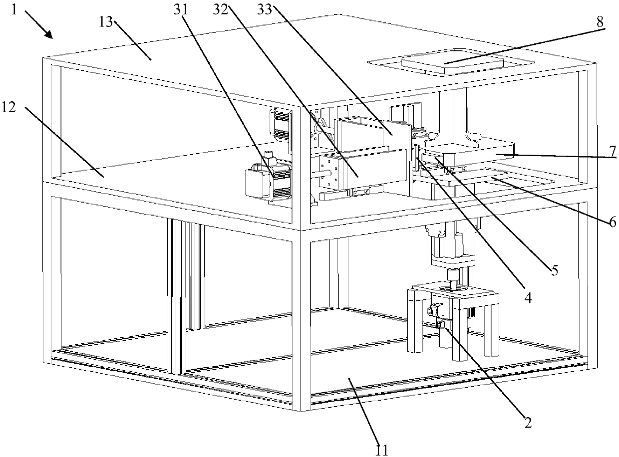
[0025] A three-axis vibration test bench of the present invention includes a frame body 1, a bottom carrier plate 6 driven to move up and down, and a bottom carrier plate 6 arranged above the bottom carrier plate and driven to translate relative to the bottom carrier plate. The top carrier plate 7, the test platform 8 fixedly arranged on the top carrier plate, and the cross guide mechanism, the cross guide mechanism includes correspondingly arranged on the two groups of vertical and spaced linear guides 5 , an intermediate plate 4 located between two sets of linear guides, and guides respectively provided on both sides of the intermediate plate and correspondingly matched with the linear guides, the bottom carrier plate and A cross guide mechanism is arranged between the top carriers, and the set of linear guides 5 are respectively fixed on adjacent surfaces of the bottom carrier and the top carrier. The middle board is located between the bottom carrier board and the top carr...

Embodiment 2

[0030] On the basis of the above-mentioned embodiments, the drive mechanism for driving the top carrier plate to move relative to the bottom carrier plate includes a horizontal drive mechanism and a longitudinal drive mechanism, which respectively include a translational drive motor 31, and the reciprocating linear motion is driven by the translational drive motor. The slide plate 33, the cross guide mechanism is arranged between the slide plate and the top carrier plate. One set of linear guides of the cross guide mechanism is correspondingly arranged on the horizontal side of the top carrier plate, and another set of corresponding linear guides is vertically arranged on the slide plate 33. The horizontal drive mechanism and the longitudinal drive structure The linear guides are located on two adjacent sides on the top carrier side. A cross guide mechanism is set between the slide plate and the top carrier plate, which can satisfy the vertical and horizontal linear motions of...

Embodiment 3

[0033] On the basis of the above embodiments, the driving mechanism for driving the bottom carrier to move up and down includes a lifting drive motor 2 fixedly arranged on the bottom platform of the frame, and the lifting frame that moves up and down is driven by the lifting drive motor. , the bottom carrier plate is fixed on the lifting frame, a guide rail slider structure is arranged between the lifting frame and the middle platen, and the lifting drive motor drives the lifting frame through a screw nut mechanism Reciprocating up and down motion. At the same time, it also includes a controller controllably connected with the lifting drive motor and the translation drive motor. Further, an exciter controlled by the above-mentioned controller can also be provided, the exciter is arranged on the top carrier plate, and is arranged between the top carrier plate and the test piece to provide low-frequency or high-frequency vibration, so that it can be stacked Four types of vibrat...


PUM


Abstract

The invention discloses a three-axis vibration test table and a control method. The three-axis vibration test table comprises a frame body, a bottom carrier board, a top carrier board, a test platformand a cross guide mechanism, wherein the bottom carrier board is driven to take a translational motion up and down; the top carrier board is arranged above the bottom carrier board and can be drivento take a translational motion relative to the bottom carrier board; the test platform is fixedly arranged on the top carrier board; the cross guide mechanism comprises two groups of linear guide parts correspondingly and perpendicularly arranged at an interval, a middle plate positioned between the two groups of linear guide parts and guide parts respectively arranged on two lateral surfaces of the middle plate and correspondingly matched with the linear guide parts; and the cross guide mechanism is arranged between the bottom carrier board and the top carrier board. The three-axis vibrationtest table is high in expansibility; and when the three-axis vibration test table is used as a vibration source, a workpiece can be additionally and randomly arranged on a vibration platform and for example, a high-frequency vibrator is additionally arranged, so that application of the three-axis vibration test table is further expanded.

Description

technical field [0001] The invention belongs to the technical field of product detection, and in particular relates to a three-axis vibration test bench and a control method. Background technique [0002] Servo three-axis vibration is a technical upgrade of the vibration of the general automotive turbocharger pipeline system. It is mainly used in the vibration fatigue test of soft and hard pipelines in the automotive turbine system to verify the performance and service life of the turbine pipeline. [0003] The natural vibration experienced by the product under actual working conditions is the composite vibration of the X, Y, and Z axes. Due to the limitation of test equipment and means, the vibration test device can only simulate the vibration of a single axis. Therefore, the general practice of the existing vibration test is: successively conduct uniaxial vibration tests on a certain product, and then comprehensively evaluate the anti-vibration performance of the product b...

Claims


Application Information

Patent Timeline
IPC IPC(8): G01M7/06
CPCG01M7/06
Inventor 肖庆
Owner 天津格特斯检测设备技术开发有限公司
Why Eureka
Try Eureka