FPC component mounting process

A component and patch technology, which is applied in the field of FPC component patch technology, can solve the problems of falling off solder joints, the welding performance cannot reach the ideal index, dead lights, etc., and achieves the effect of strengthening thrust and ensuring production quality.

Inactive Publication Date: 2019-03-29
SHENZHEN TECHASER TECH
View PDF5 Cites 5 Cited by
  • Summary
  • Abstract
  • Description
  • Claims
  • Application Information

AI Technical Summary

Problems solved by technology

In the current FPC placement process, it is necessary to evaluate the welding strength of components welded on the FPC. One of the criteria is the forward thrust of the LED; When the required thrust is greater than the LED welding strength, the welding point may fall off, resulting in LED dead light. With the rapid development of the electronic manufacturing industry, the surface mount tech

Method used


Image

  • FPC component mounting process
  • FPC component mounting process
  • FPC component mounting process

Examples


Embodiment 1

[0026] Such as Figure 1-2 Show.

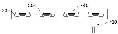
[0027] S1. Fixing, fixing the back of the FPC board on the positioning fixture, the optical camera detects the circuit and position of the FPC board, and prepares for the welding of the components 30 .

[0028] S2. Glue printing. After the optical camera detects the FPC board 10 correctly, paste the first stencil plate (not shown) on the front of the FPC board 10 , and perform stencil printing on the FPC board 10 through the glue dispensing station 40 .

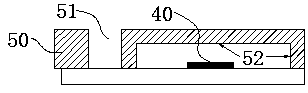
[0029] S3, solder paste printing, the second stencil 50 is placed above the first stencil, and the second stencil is provided with a mesh 51 and an empty groove 52 at the position corresponding to the dispensing position 40, so that the solder paste 20 Missing printing to the preset position of the FPC board 10.

[0030] S4. Mounting, sending the FPC board 10 after the solder paste 20 printing step into the placement machine, and the placement machine accurately installs the components 30 ...

Embodiment 2

[0040] Such as Figure 1-2 Shown:

[0041] S1. Fixing, fixing the back of the FPC board on the positioning fixture, the optical camera detects the circuit and position of the FPC board, and prepares for the welding of the components 30 .

[0042] S2. Glue dispensing. After the optical camera detects the FPC board 10 correctly, the glue dispenser dispenses glue at the preset position of the FPC board 10 .

[0043] S3, solder paste printing, the second stencil is placed on the side where the glue is printed, and the second stencil is provided with an avoidance groove 52 at the position corresponding to the dispensing position 40, so that the solder paste can be missed printed on the FPC board 10 default position.

[0044] S4. Mounting, sending the FPC after the solder paste 20 printing step into the placement machine, and the placement machine accurately installs the components 30 to the fixed position of the FPC board 10 .

[0045] S5. Curing, sending the mounted circuit boa...


PUM


Abstract

The invention relates to an FPC component mounting process, which comprises the following steps: S1, FPC board fixing; S2, glue printing; S3, solder paste printing; S4, mounting; S5, solidifying; S6,intermediate inspection; S7, reflow soldering; and S8, product detection, and process completion. A double-steel-mesh design is adopted in the process. Glue and solder paste are skip-printed at presetpositions of an FPC board in turn. The solder paste steel mesh plate adopts a clearance design, so that the dispensing position and the solder paste steel mesh do not interfere with each other. The component mounting thrust is strengthened. The manufacture quality of the circuit board is ensured. The technical problem that the current LED or capacitor mounting thrust is not up to the standard issolved. The FPC component mounting process is applicable to large-scale efficient production.

Description

technical field [0001] The invention belongs to the technical field of SMT (surface mount technology), and relates to a FPC component patching process. Background technique [0002] With the development of electronic products in the direction of short, light and thin, correspondingly, the integration and miniaturization of electronic components are required. Traditional through-hole mounting technology (THT) can no longer meet the requirements, and a new generation of placement technology, namely surface mount technology (SMT), has emerged as the times require. From a broad perspective, SMT includes surface mount components (SMC: Surface Mount Component), surface mount devices (SMD: Surface Mount Device), surface mount printed circuit boards (SMB: Surface Mount Printed Circuit Board), ordinary Mixed printed circuit board (PCB: Printed CircuitBoard), dispensing, paste, surface mount equipment, component pick and place system, welding and online testing and other technical co...

Claims


Application Information

Patent Timeline
IPC IPC(8): H05K3/34
CPCH05K3/341
Inventor 熊远江陈武金莹
Owner SHENZHEN TECHASER TECH
Why Eureka
Try Eureka