Continuous-output static-hydrogen compression, storage and filling integration system

An output, static technology, applied in pipeline systems, hydrogen technology, gas/liquid distribution and storage, etc., can solve the problems of small compression ratio range, large system volume, etc., to achieve improved practicability, low leakage risk, enhanced hydrogen The effect of compression and delivery capacity

Pending Publication Date: 2019-04-05
GUANGDONG INST OF RARE METALS
View PDF6 Cites 4 Cited by
  • Summary
  • Abstract
  • Description
  • Claims
  • Application Information

AI Technical Summary

Problems solved by technology

[0005] Due to structural design reasons, the compression ratio range of the mechanical hydrogen compression system is usually small. To achieve a higher pressure output, it often requires the cooperation of more stages of different types of mechanical hydrogen compressors to achieve it. lead to bulky system
In addition, the traditional mechanical compression scheme itself does not involve the storage function of hydrogen, which requires a large storage tank to meet its use requirements
[0006] With the increasing demand for high-pressure hydrogen in the market, the shortcomings of traditional mechanical hydrogen compression methods have been increasingly exposed

Method used


Image

  • Continuous-output static-hydrogen compression, storage and filling integration system
  • Continuous-output static-hydrogen compression, storage and filling integration system
  • Continuous-output static-hydrogen compression, storage and filling integration system

Examples


Embodiment 1

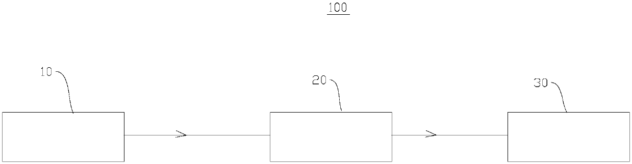
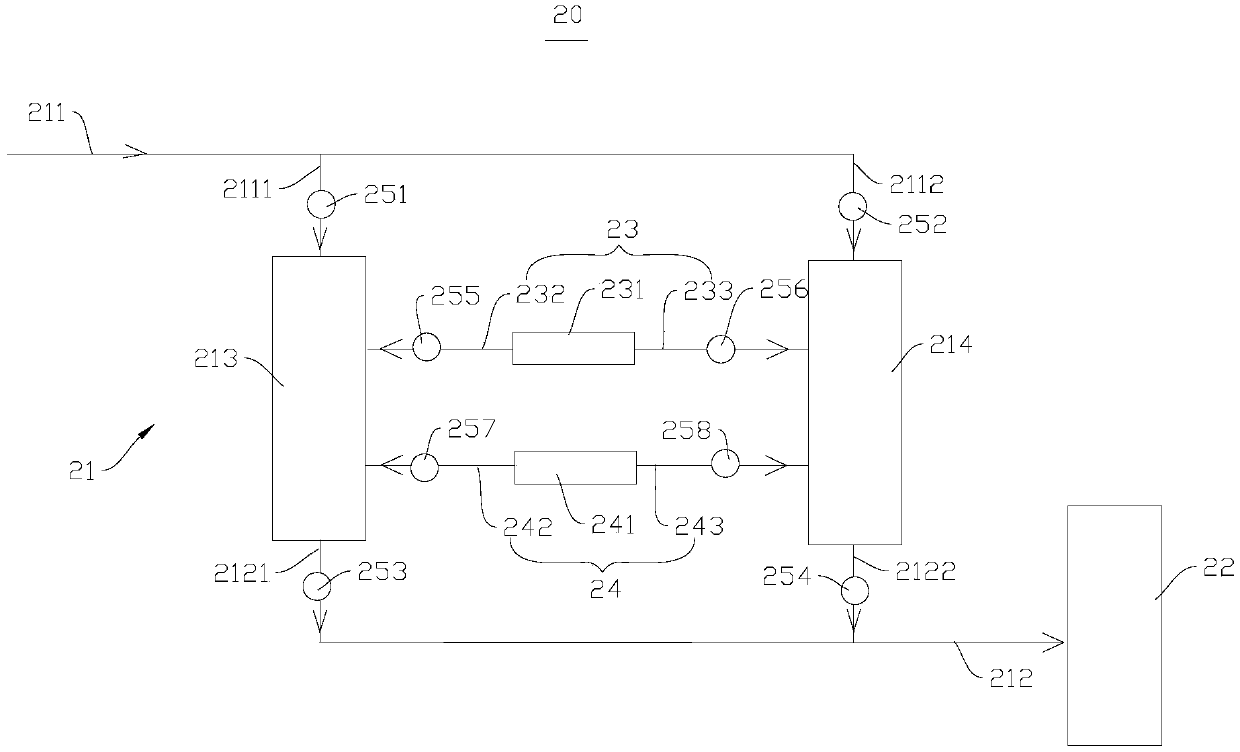
[0085] This embodiment provides a continuous output static hydrogen compression, storage, and filling integrated system 100, which includes a hydrogen source input device 10, a hydrogen pressurization and storage unit 20, and a filling device 30. Among them, the hydrogen pressurization and storage unit 20 includes a static hydrogen compression device 21 (the device contains two compression tanks, namely the first hydrogen compression tank 213 and the second hydrogen compression tank 214) and a pressurized hydrogen storage device 22 (1 pressure storage tank included).

[0086] The input hydrogen source of the system is the hydrogen produced by the electrolytic water hydrogen production device, and the input pressure is 4MPa. Both the first hydrogen compression tank 213 and the second hydrogen compression tank 214 are filled with a rare earth-titanium complex phase hydrogen storage alloy. Water is used as the cold and heat medium, and the heat source comes from ordinary indust...

Embodiment 2

[0089] This embodiment provides a continuous output static hydrogen compression, storage, and filling integrated system 100, which includes a hydrogen source input device 10, two hydrogen pressurization and storage units 20, and a filling device 30. Wherein, each hydrogen pressurization and storage unit 20 includes a static hydrogen compression device 21 (each static hydrogen compression device 21 contains two compression tanks, i.e. the first hydrogen compression tank 213 and the second hydrogen compression tank 214 ) and a pressurized hydrogen storage device 22 (each pressurized hydrogen storage device 22 contains a pressure storage tank). The two static hydrogen compression devices 21 are respectively low pressure stage (output pressure 25MPa) and high pressure stage (output pressure 42MPa). Two pressurized hydrogen storage devices 22 are used to store compressed hydrogen in each stage.

[0090] The input hydrogen source of the system is hydrogen transported by tank truck...

Embodiment 3

[0099] This embodiment provides a continuous output static hydrogen compression, storage, and filling integrated system 100, the integrated system includes a hydrogen source input device 10, 3 arrays of hydrogen pressurization and storage units 20, and 3 sets of filling device 30. Wherein, each hydrogen pressurization and storage unit 20 array includes an array of static hydrogen compression devices 21 (each static hydrogen compression device 21 contains two compression tanks, i.e. the first hydrogen compression tank 213 and the second hydrogen compression tank 213). tank 214) and an array of pressurized hydrogen storage devices 22 (each pressurized hydrogen storage device 22 contains a pressure storage tank). The three arrays of static hydrogen compression devices 21 are respectively low-pressure stage (output pressure 25MPa), medium-pressure stage (output pressure 42MPa) and high-pressure stage (output pressure 90MPa). Three arrays of pressurized hydrogen storage devices 22...


PUM


Abstract

The invention provides a continuous-output static-hydrogen compression, storage and filling integration system and belongs to the technical field of hydrogen fuel. The integration system includes a hydrogen source input device, a filling device and at least one hydrogen boosting and storage unit, wherein each hydrogen boosting and storage unit includes a static-hydrogen compression device and a pressurized-hydrogen storage device; the static-hydrogen compression device correspondingly communicates with a hydrogen source input device and the pressurized-hydrogen storage device; and the pressurized-hydrogen storage device further communicates with the inlet end of the filling device or the hydrogen inlet end of the next static-hydrogen compression device. The integration system has no movingparts, completely uses a heat driving method to realize the pressurizing of hydrogen, has compact and quiet design, high reliability and low risk of leakage, can simultaneously improve the purity ofhydrogen in the process of compression, and realizes the continuous output of compressing hydrogen through the hydrogen sucking and discharging method of alternating multiple tanks; and when multiplestages are in parallel operation, the hydrogen compression and conveying capacity of the system is greatly improved and the practicability is improved.

Description

technical field [0001] The invention belongs to the technical field of hydrogen fuel, and in particular relates to a continuous output static hydrogen compression, storage and filling integrated system. Background technique [0002] Any device driven by hydrogen fuel cells, such as fuel cell vehicles, backup power sources, etc., needs to use hydrogen and oxygen as its "fuel". Oxygen can be obtained from the air, while hydrogen needs to be stored in advance. When needed Release it again. At present, the high-pressure hydrogen technology solution has become the first solution for the fuel cell hydrogen supply system due to its mature technical route and good dynamic response performance of the hydrogen supply system. [0003] The most mature method of generating high-pressure hydrogen currently on the market mainly adopts the method of mechanical compression, which causes the volume change of the gas storage space through the movement of the piston or diaphragm, thereby short...

Claims


Application Information

Patent Timeline
Patent Type & Authority Applications(China)
IPC IPC(8): F17D1/07F17D3/01
CPCF17D1/07F17D3/01Y02P90/45Y02E60/34
Inventor 孙泰唐仁衡肖方明王英李睿
Owner GUANGDONG INST OF RARE METALS
Why Eureka
Try Eureka