
Semiconductor device and forming method thereof

A semiconductor and device technology, applied in the field of semiconductor devices and their formation, can solve problems such as poor performance of semiconductor devices, and achieve the effects of avoiding expansion and contraction, improving mobility, and avoiding losses.

Inactive Publication Date: 2019-04-05
SEMICON MFG INT (SHANGHAI) CORP +1
View PDF23 Cites 0 Cited by
  • Summary
  • Abstract
  • Description
  • Claims
  • Application Information

AI Technical Summary

Problems solved by technology

[0004] However, the performance of semiconductor devices composed of MOS transistors formed in the prior art is poor

Method used


Image

  • Semiconductor device and forming method thereof
  • Semiconductor device and forming method thereof
  • Semiconductor device and forming method thereof

Examples


Embodiment Construction

[0032] As mentioned in the background, semiconductor devices formed in the prior art have poor performance.

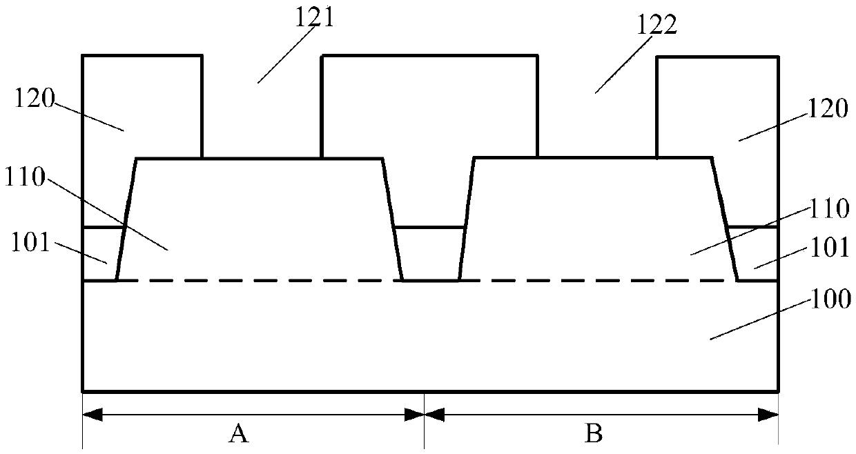
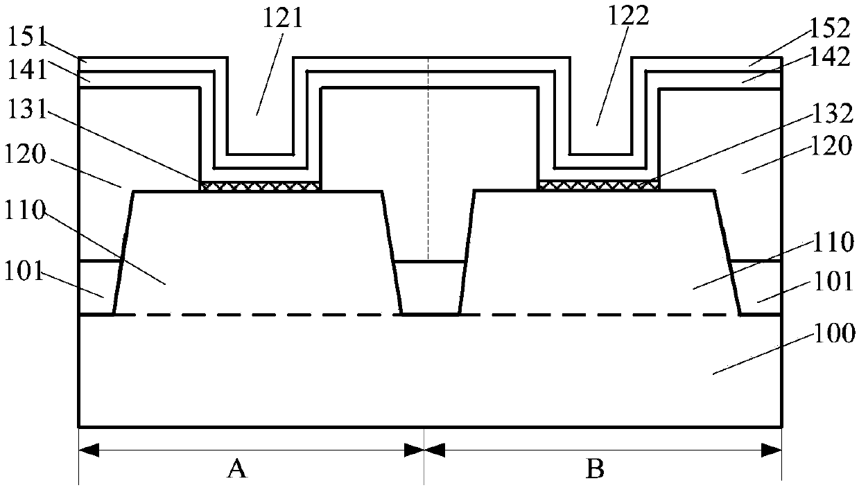
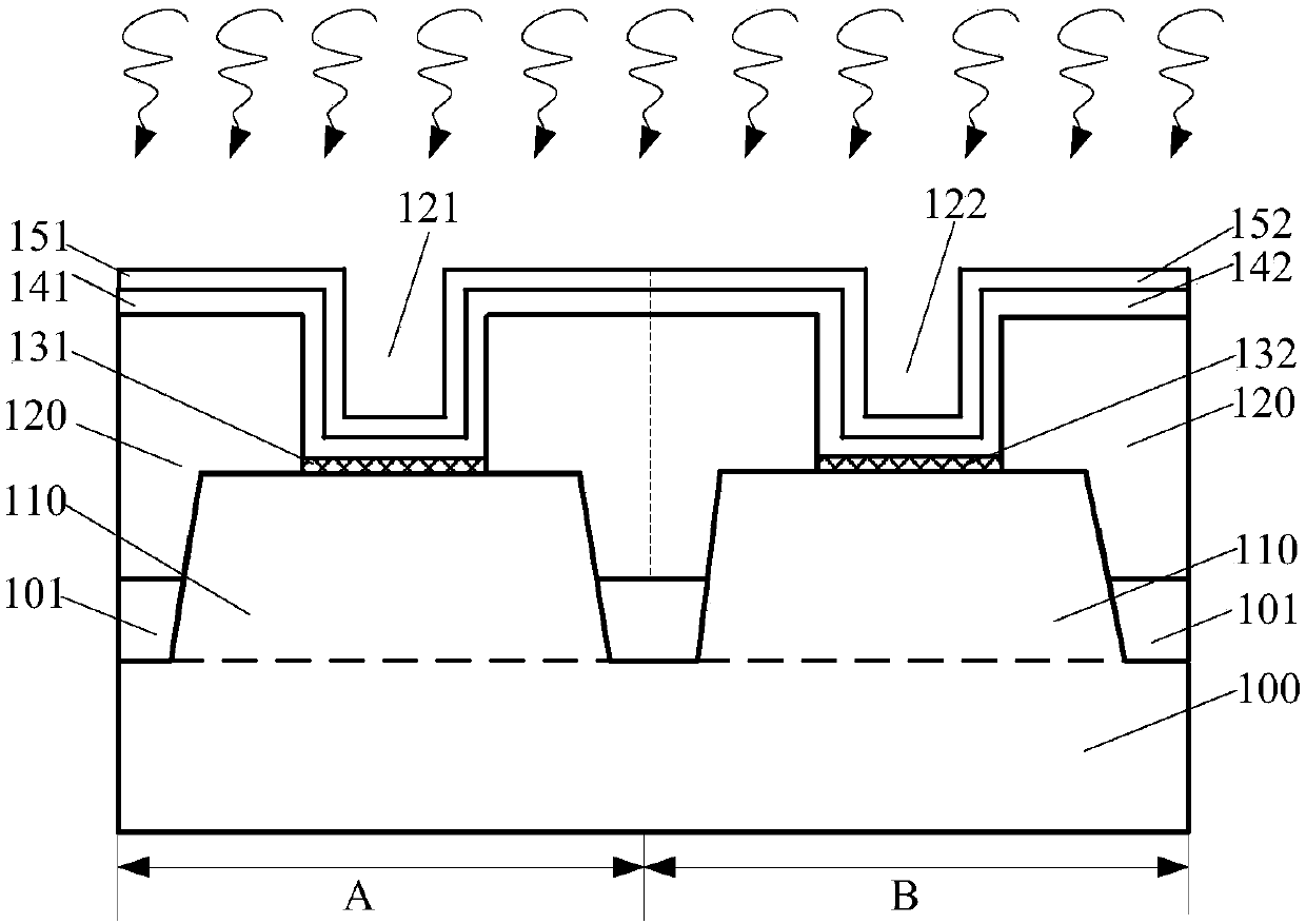
[0033] A method for forming a semiconductor device, comprising: providing a substrate; forming a dummy gate structure on the substrate; forming a source-drain doped layer in the substrate on both sides of the dummy gate structure; forming a dielectric layer covering the sidewall of the dummy gate structure; after forming the dielectric layer, removing the dummy gate structure and forming a gate opening in the dielectric layer; forming an interface layer at the bottom of the gate opening; annealing the interface layer; forming the interface layer, A gate electrode layer is formed in the gate opening.

[0034] However, the performance of the semiconductor device formed by the above-mentioned method is relatively poor. After research, it is found that the reasons are:

[0035] Annealing is performed on the interface layer to densify the interface layer, thereby reducing ...


PUM

PropertyMeasurementUnit
Thicknessaaaaaaaaaa
Thicknessaaaaaaaaaa

Abstract

The invention provides a semiconductor device and a forming method thereof. The method comprises the following steps that a substrate is provided; a dielectric layer is formed on the substrate, wherein a first gate opening which penetrates through the dielectric layer is formed in the dielectric layer; a first interface layer is formed at the bottom of the first gate opening; a first gate dielectric layer is formed on the side walls and the bottom of the first gate opening, wherein the first gate dielectric layer is located on the first interface layer; annealing treatment is carried out on the first interface layer; after annealing treatment is carried out, a first gate electrode layer located on the first gate dielectric layer is formed in the first gate opening; first through holes areformed in the dielectric layer on the two sides of the first gate electrode layer; and a first source drain doping layer is formed in the substrate at the bottoms of the first through holes. Accordingto the method, the performance of the semiconductor device is improved.

Description

technical field [0001] The invention relates to the field of semiconductor manufacturing, in particular to a semiconductor device and a forming method thereof. Background technique [0002] MOS transistors are one of the most important components in modern integrated circuits. The basic structure of a MOS transistor includes: a semiconductor substrate; a gate structure located on the surface of the semiconductor substrate; a source region located in the semiconductor substrate on one side of the gate structure; and a drain region located in the semiconductor substrate on the other side of the gate structure. [0003] The working principle of the MOS transistor is: by applying a voltage to the gate structure, the current in the channel at the bottom of the gate structure is adjusted to generate a switching signal. [0004] However, the performance of semiconductor devices formed by MOS transistors formed in the prior art is relatively poor. Contents of the invention [00...

Claims


Application Information

Patent Timeline
IPC IPC(8): H01L29/78H01L29/423H01L29/06H01L21/336
CPCH01L29/0684H01L29/4232H01L29/66477H01L29/78
Inventor 周飞
Owner SEMICON MFG INT (SHANGHAI) CORP
Learn More