

A kind of inalsb infrared detector surface passivation method
An infrared detector and detector chip technology, applied in the field of infrared detectors, can solve the problems of low reliability, high power consumption of infrared detector components, large volume, etc., to increase surface resistivity, reduce surface recombination rate and surface Effect of leakage current
Active Publication Date: 2021-04-20
CHINA AIR TO AIR MISSILE INST
View PDF4 Cites 0 Cited by
- Summary
- Abstract
- Description
- Claims
- Application Information
AI Technical Summary
Problems solved by technology
However, the harsh working environment leads to high power consumption, large size, high cost, and low reliability of the infrared detector components as a whole, which brings inconvenience to the practical application of airborne, spaceborne, and missile-borne infrared detectors
Method used
View moreImage
Smart ImageViewing Examples

Examples
Embodiment 1
[0034]Example 1 The inalsb infrared detector chip passes the test results completed by optical and electrical test equipment:
[0035]Table 1 Performance test results of the infrared device of the above embodiment
[0036]
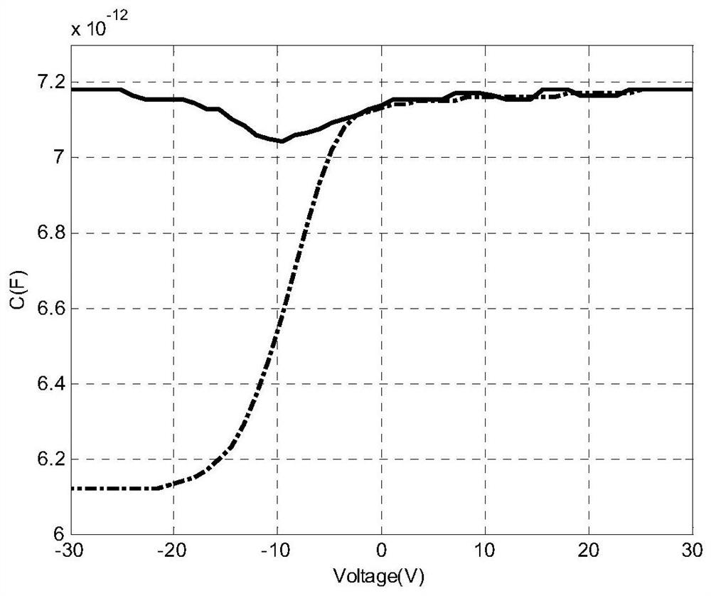
[0037]Table 2. MIS structure calculation results of the passivation film of the above embodiment
[0038]
[0039]By test structure analysis of Table 1, Table 2, the passivation method has a good passivation effect on the surface of the INALSB material, which can effectively reduce surface composite rates and increase surface resistance.
Login to View More PUM
| Property | Measurement | Unit |
|---|---|---|
| thickness | aaaaa | aaaaa |
Abstract
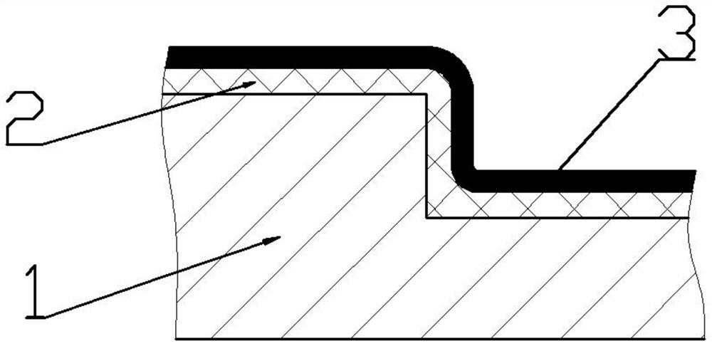
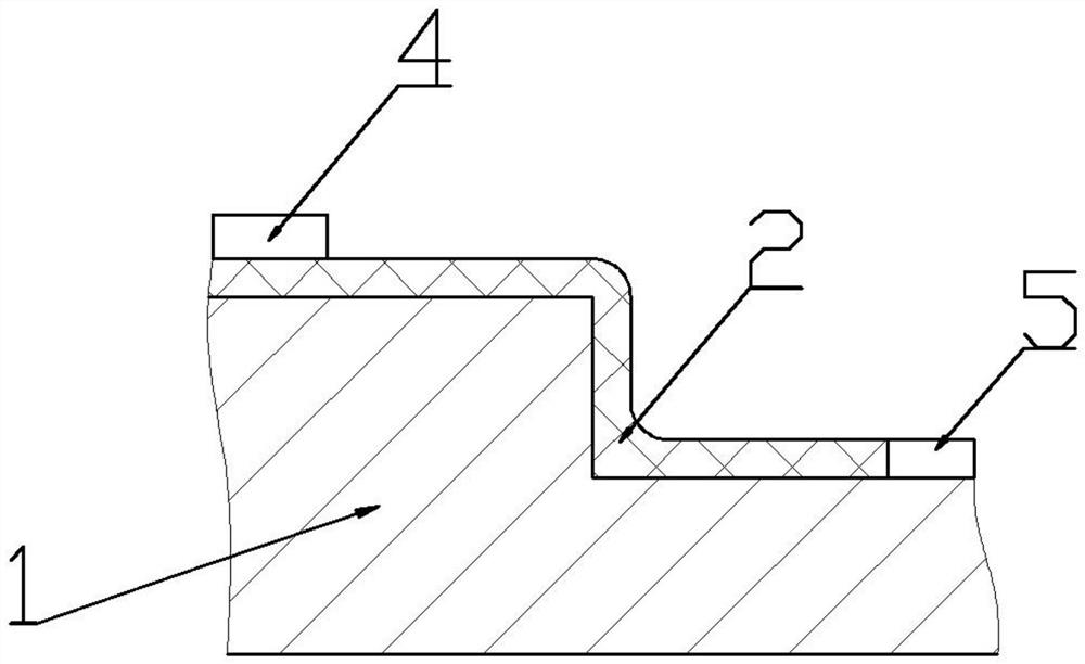
The invention relates to a method for passivating the surface of an InAlSb infrared detector. The steps are as follows: step 1: soaking the InAlSb detector chip in an organic solvent; step 2: soaking the InAlSb detector chip in an acidic solution; step 3 : Put the InAlSb detector chip into the anodizing solution, set the anodizing current and connect the metal electrode, when the resistance value on the surface of the chip reaches the set value, cut off the anodizing power supply to form an anodizing film; step 4: cleaning InAlSb detector chip; step five: put it into PECVD equipment, and prepare a dielectric film. The method can effectively reduce the leakage current on the surface of the infrared detector and improve the impedance of the device.
Description
Technical field[0001]The present invention relates to the field of infrared detectors, and more particularly to an INALSB infrared detector surface passivation method.Background technique[0002]Infrared light is an important part of the electromagnetic spectrum, with its wide-wave, medium wave, long wave and other bands to the target characteristics unique reflection in military sectors, such as single combat, precise guidance, infrared warning, satellite mapping Wait. At present, high-performance military infrared detectors are low-temperature refrigeration to reduce the noise of the device to improve the signal-to-noise ratio of the infrared detector. However, the harsh working environment makes the overall power consumption of the infrared detector assembly, high volume, low cost, low reliability, giving the airborne, on-white, and bourse, the actual application of the bunker.[0003]Take the target detection and infrared guidance in modern aviation as an example. With the developme...
Claims
Login to View More Application Information
Patent Timeline
 Patent Type & AuthorityPatents(China)
IPC IPC(8): H01L31/18H01L31/0236H01L31/0216C30B33/10
CPCC30B33/10H01L31/02167H01L31/02363H01L31/1844H01L31/1876Y02P70/50
Inventor李墨吕衍秋朱旭波张利学王郁波
OwnerCHINA AIR TO AIR MISSILE INST