Structure of prefabricated precast concrete retaining wall bottom plate and vertical plate

A prefabricated concrete and retaining wall technology, applied in the construction field, can solve problems such as insufficient bolt anchorage length, affecting the strength of the retaining wall, and affecting the production period, so as to save labor, shorten the construction period, and reduce labor intensity.

Pending Publication Date: 2019-04-09
上海浦河工程设计有限公司
View PDF5 Cites 0 Cited by
  • Summary
  • Abstract
  • Description
  • Claims
  • Application Information

AI Technical Summary

Problems solved by technology

The welding method needs to be welded on site, the process will be restricted by various conditions on site, and part of the cast-in-place is required after welding; the laminated plate method needs to be cast-in-place on the base plate, and it does not mean that assembly can be assembled, which will inevitably affect the production schedule The anchor bolt method at the bottom corner of the vertical slab is to thicken the bottom corner of the vertical slab and reserve bolt holes at the bottom corner, and connect through the bolts embedded in the bottom plate. However, because the anchoring position is at the bottom corner, the anchoring length of the bolt is insufficient. Affects the strength of the retaining wall and poor labor conditions

Method used


Image

  • Structure of prefabricated precast concrete retaining wall bottom plate and vertical plate
  • Structure of prefabricated precast concrete retaining wall bottom plate and vertical plate
  • Structure of prefabricated precast concrete retaining wall bottom plate and vertical plate

Examples


Embodiment 1

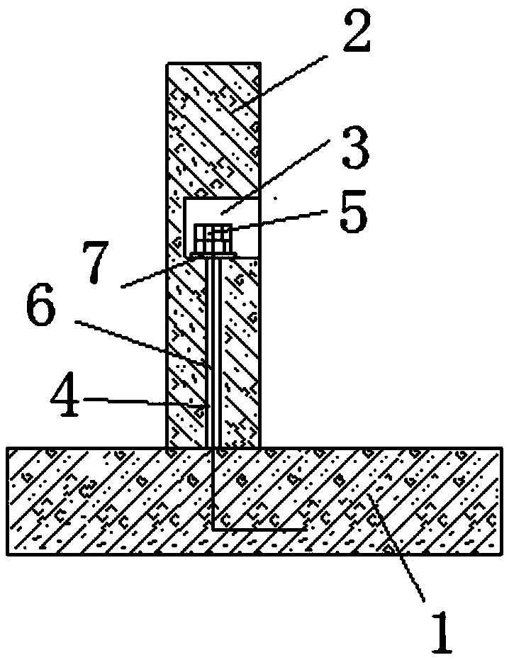
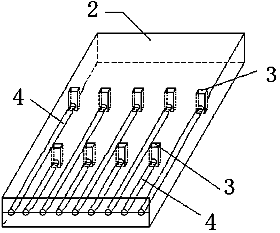
[0024] Embodiment 1: as figure 1 As shown, a prefabricated prefabricated concrete retaining wall base plate and vertical wall structure, including the retaining wall base plate 1 and the retaining wall vertical plate 2, the vertical plate 1 is reserved according to the set one-word equidistant array orientation The hole 3 communicates with the anchor hole 4, and the anchor hole 4 communicates with the nut hole 3, and the height of the nut hole 3 is greater than the sum of the heights of the three nuts 5. An anchor 6 is pre-embedded in the bottom plate 1 according to the same orientation. The anchor 6 has sufficient length and its top end passes through the anchor hole 4 to be fixedly connected with the double nut 5 and the washer 7 inserted into the nut hole 3. The nut 5. Double nuts are used to superimpose and tighten each other to resist shearing and loosening.

[0025] The connection between the long enough anchor 6 and the nut 5 not only avoids on-site welding and casting...

Embodiment 2

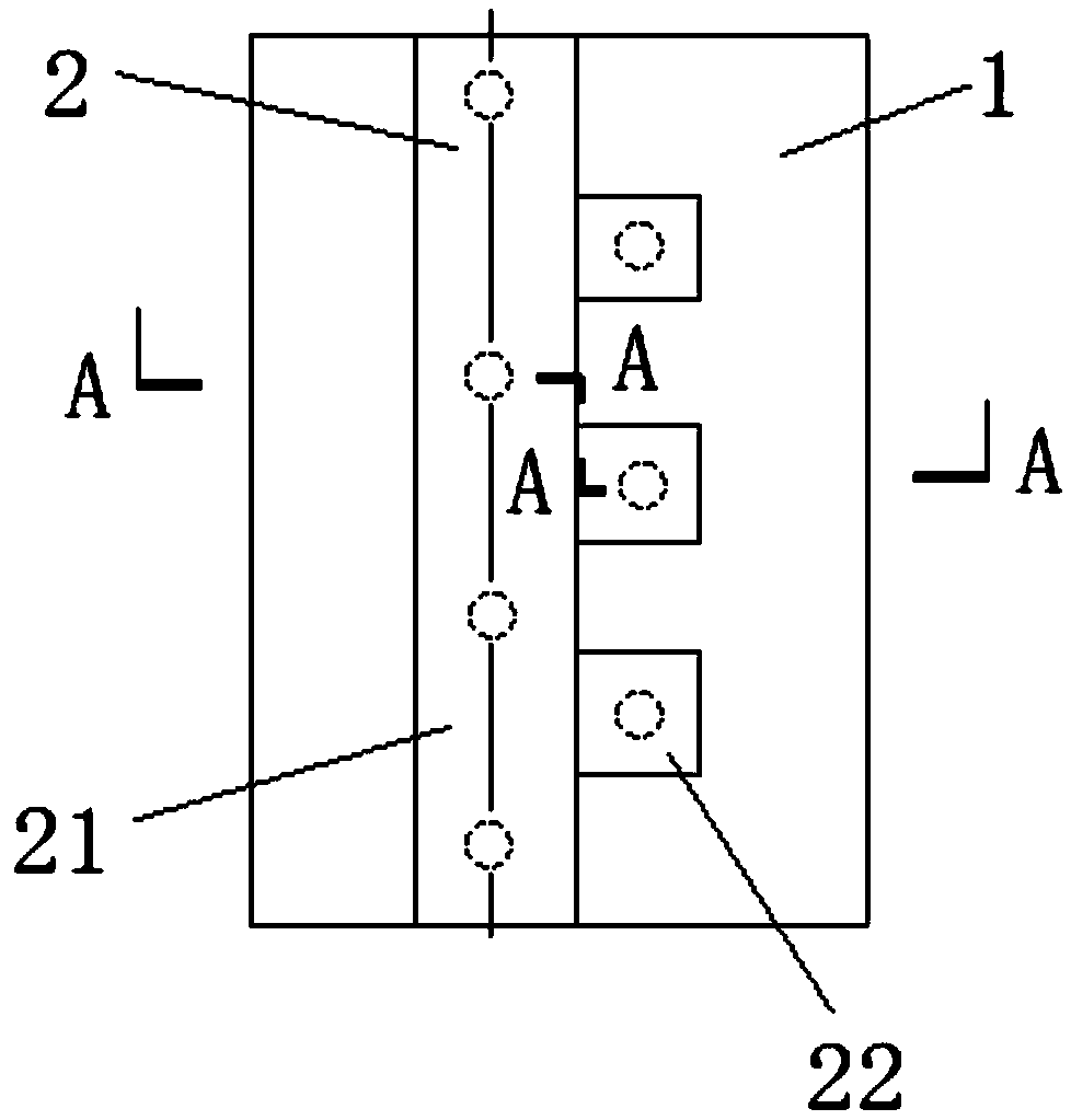
[0028] Embodiment 2: the vertical plate 2 is formed by integral casting of the main board 21 and the steps 22, and several steps 22 are arranged according to the specific conditions, and the height of the steps 22 is lower than the main board 21, and the nut holes 3 and the The orientations of the anchor holes 4 and the anchors 6 are staggered according to a triangle relationship, and the position of the apex of the triangle relationship corresponds to the center point of the step 22 . Since the cantilever or buttress retaining wall is a bending-shear component, the prefabricated parts are generally split at the intersection of the vertical plate 2 and the bottom plate 1. reliability, it is meaningful to add a step 22 on the rear side of the bottom of the vertical plate 2 for bending and shearing resistance, and the rest of the structure is the same as that of embodiment 1, see image 3 , Figure 4 ,in image 3 The small and medium circles show the distribution positions of ...


PUM


Abstract

The invention discloses a structure of a prefabricated precast concrete retaining wall bottom plate and vertical plate. The structure comprises a retaining wall bottom plate and a retaining wall vertical plate, wherein a nut hole and a ground anchor hole are reserved in the vertical plate according to set orientation; the ground anchor hole communicates with the nut hole; a ground anchor is correspondingly pre-embedded in the same direction in the bottom plate; the ground anchor has a sufficient length and the top end of the ground anchor passes through the ground anchor hole to be fixedly connected and matched with a nut inserted into the nut hole. According to the invention, the structure and the process of a retaining wall are improved, the field welding and the cast-in-place are avoided, the construction period is shortened, the ground anchor is rationally arranged, the strength is reliable, and the structure has the advantages of saving labor capacity and reducing labor intensity.

Description

technical field [0001] The invention relates to the technical field of construction, in particular to a structure of a prefabricated concrete retaining wall. Background technique [0002] The retaining wall is a common structure in the construction of roads, railways, municipalities, water conservancy and other industries. It is mainly used to resist the earth pressure behind the wall and maintain the stability of the engineering structure behind the wall. Although various forms of retaining structures have been developed, the grouted rubble (block stone) gravity retaining wall is still the most widely used in engineering. This kind of retaining wall has the advantages of convenient materials, simple process, and wide application range, but has the disadvantages of large material consumption and low degree of mechanization, which makes the labor intensity of workers high, low efficiency, and many sequelae during construction. [0003] Prefabrication is an important way to i...

Claims


Application Information

Patent Timeline
Patent Type & Authority Applications(China)
IPC IPC(8): E02D29/02
CPCE02D29/02
Inventor 盛军付明军丁荣宗张桂春孙耀文姜哲叶寅许杰梁亮赵金梅
Owner 上海浦河工程设计有限公司
Why Eureka
Try Eureka