Novel drilling machine

A drilling machine, a new type of technology, applied in the direction of boring machine/drilling machine parts, boring/drilling, drilling/drilling equipment, etc., can solve the problem that the bench drill has no low-speed and high-speed adjustment function, and it is difficult Precise control, improving production costs and other issues, to achieve the effect of rational use of electric energy, good processing performance, and improvement of processing efficiency

Active Publication Date: 2019-04-12
ZHEJIANG XILING
View PDF7 Cites 3 Cited by
  • Summary
  • Abstract
  • Description
  • Claims
  • Application Information

AI Technical Summary

Problems solved by technology

When the power supply voltage is unstable, or the influence of external force, or the material hardness of the workpiece is uneven, the speed of the drilling machine will be unstable and the cutting quality will be affected.
This greatly affects the production

Method used


Image

  • Novel drilling machine
  • Novel drilling machine
  • Novel drilling machine

Examples


Embodiment 1

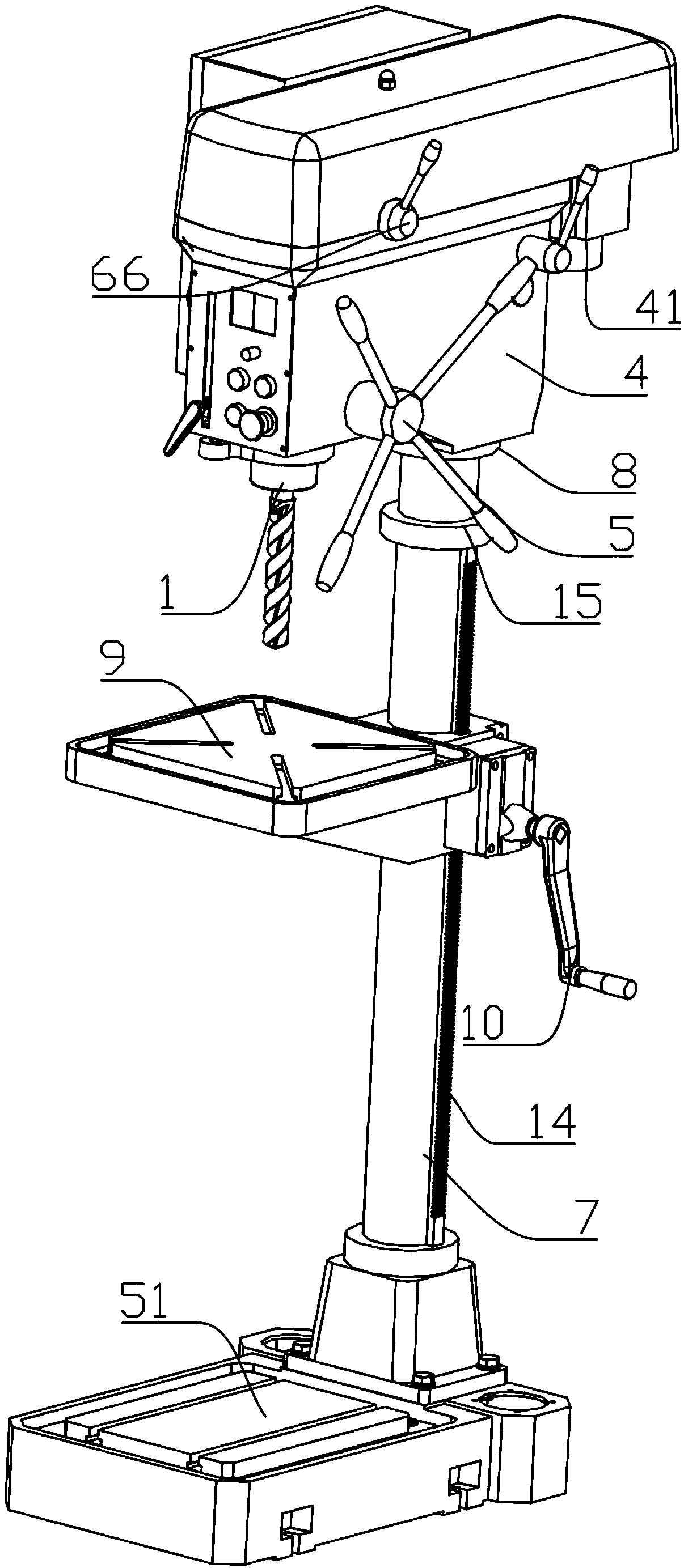
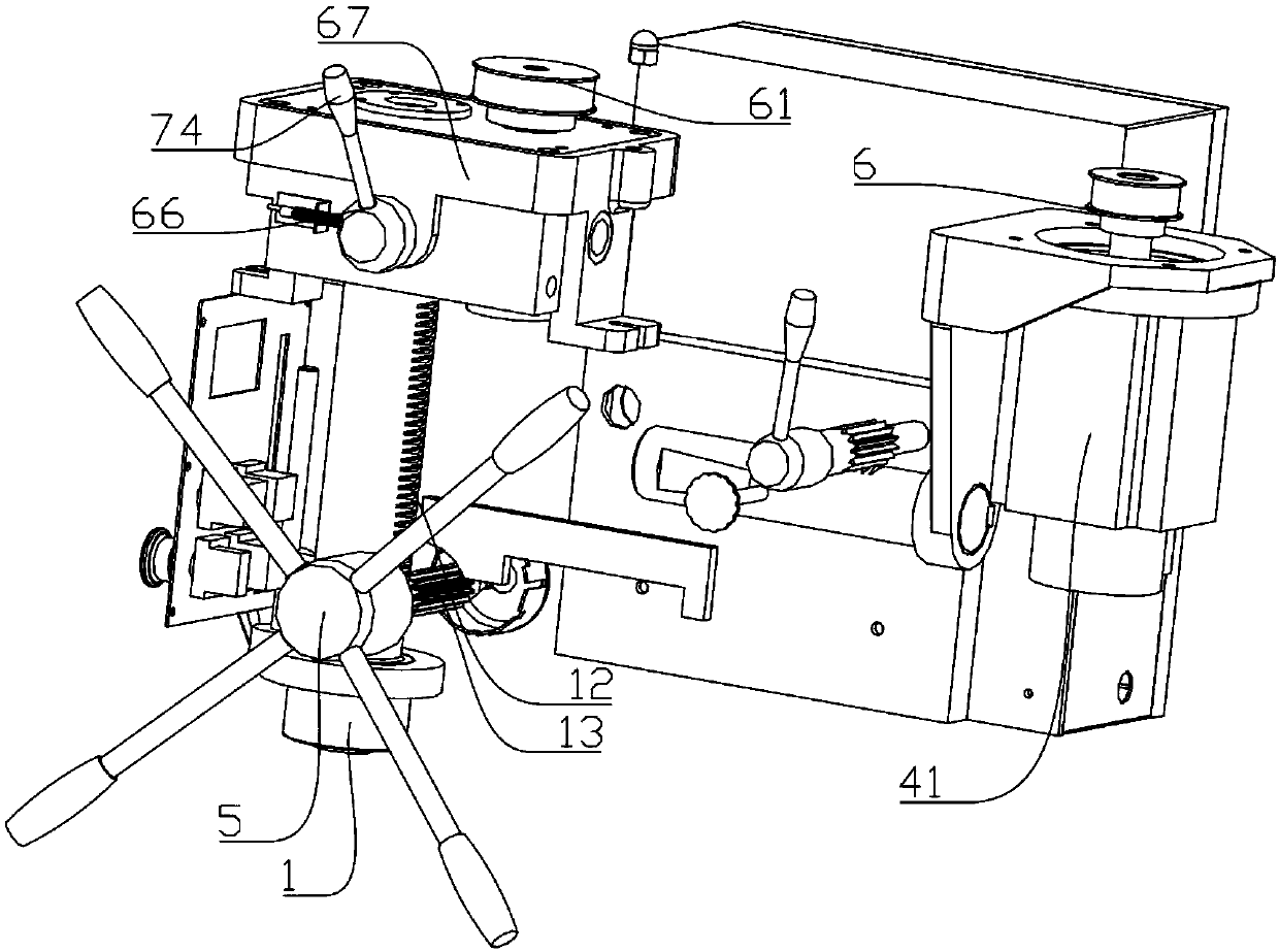
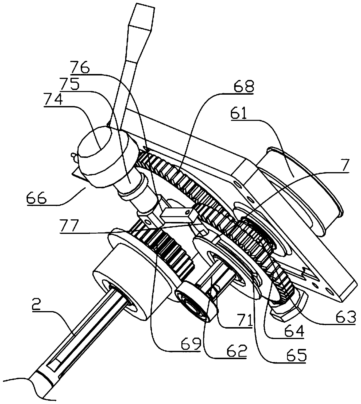
[0033] Embodiment one: if Figure 1-6 As shown, a novel drilling machine includes a base 51, a support rod 7, a workbench 9 and a machine head. The base 51 is provided with a support rod 7, and the support rod 7 is provided with a workbench 9. The work One side of the table 9 is provided with a rotary rocker 10 capable of controlling the sliding of the workbench 9 on the support column 7, and the upper end of the support column 7 is equipped with a machine head through a connecting flange 8, and the machine head includes a head frame 4, a set On one side of the head frame 4 and drive the rotating disk 5, the gear box 67 and the motor 41 that the main shaft 2 moves up and down, the output shaft of the motor 41 is provided with a first pulley 6, and one side of the first pulley 6 passes through The synchronous belt is provided with a second pulley 61, and a rotating shaft 62 is pierced in the second pulling wheel 61, and the rotating shaft 62 is provided with a first small gear ...

Embodiment 2

[0044] Embodiment two: if Figure 7-9 As shown, this embodiment is basically consistent with Embodiment 1, the difference is that a cooling device 79 is provided on one side of the head frame 4, and the cooling device 79 includes a box body 21, a liquid inlet 22, and a handle 23 , a fixed plate 24, a push rod 25, a liquid outlet pipe 26, a push plate 27, a first one-way valve 28, a dividing plate 29, a connecting pipe 210 and a second one-way valve 211, and the casing 21 is connected to the On one side of the head frame 4, a liquid inlet 22 is provided on the top of the box body 21, a partition 29 is arranged inside the box body 21, a communication pipe 210 is provided on the partition 29, and a second one-way valve 211 is arranged in the communication pipe 210. A push plate 27 is slidably provided between the bottom of the dividing plate 29 and the casing 21, and one end of the push plate 27 is provided with a push rod 25, and the push rod 25 passes through the casing 21, and...

Embodiment 3

[0048] Embodiment three: as Figure 10-11 As shown, this embodiment is basically the same as Embodiment 1, the difference is that a waste collection device 3 is provided on the base 51, and the waste collection device 3 includes a storage body 36, a stopper 37, a brush 38, The slag discharge port 39, the valve 310 and the first mesh plate 311, the base 51 is provided with a storage body 36 for collecting waste chips, the left and right sides of the storage body 36 are provided with limiters 37, the limiter 37 and the brush 38 are matched and connected, the lower part of the receiving body 36 is provided with a first mesh plate 311, the lower part of the right side of the receiving body 36 is provided with a slag discharge port 39, and a valve 310 is provided on the slag discharge port 39.

[0049] The waste chips and cutting fluid generated during the processing of the technical solution fall into the receiving body 36, which ensures the cleanliness of the workbench 9 and can ...


PUM


Abstract

The invention belongs to the technical field of machinery, and particularly relates to a novel drilling machine. The novel drilling machine comprises a base, a supporting rod, a working table and a machine head, the base is provided with the supporting rod, the supporting rod is provided with the working table in a sleeved mode, a rotary rocker arm is arranged on one side of the working table, themachine head is arranged at the upper end of the supporting rod in a penetrating mode, the machine head comprises a head frame, a rotary plate, a gear box and a motor, a first belt pulley is arrangedon an output shaft of the motor, one side of the first belt pulley is provided with a second belt pulley through a synchronous belt, the second belt pulley is internally provided with a rotary shaftin a penetrating mode, the rotary shaft is slidably provided with a first small gear and a first large gear from top to bottom in sequence, a stirring groove is formed in the lower part of the first large gear, andan adjusting device is mounted inside the stirring groove; the gear box is provided with a main shaft in a penetrating mode, the upper end of the main shaft is provided with a second large gear and a second small gear from top to bottom in sequence, when the adjusting device is anticlockwise rotated, the second large gear is engaged with the first small gear, when the adjusting device is clockwise rotated, the second small gear is engaged with the first large gear.

Description

technical field [0001] The invention belongs to the technical field of machinery, in particular to a novel drilling machine. Background technique [0002] At present, drilling machines are generally speed-regulated through multi-stage pulleys. Due to the structural characteristics, the speed regulation of the existing drilling machine is inconvenient. When adjusting the speed, it is necessary to remove the pulley shell and adjust the position of the belt. The speed ratio of the drilling machine has a small adjustment range, generally within 1:10. Because of the step speed regulation, the optimal speed required by the drilling machine for drilling and cutting cannot be obtained. The larger the speed ratio of the drilling machine, the larger the diameter of the pulley, which increases the volume of the drilling machine. When the power supply voltage is unstable, or the influence of external force, or the material hardness of the workpiece is uneven, the speed of the drilli...

Claims


Application Information

Patent Timeline
IPC IPC(8): B23B39/12B23B47/26B23B47/30B23Q5/16B23Q11/00B23Q11/10
CPCB23B39/12B23B47/26B23B47/30B23Q5/167B23Q11/0067B23Q11/10
Inventor 杨学良
Owner ZHEJIANG XILING
Why Eureka
Try Eureka