Injection system used gravity to realize automatic adjustment of oil field injection well and using method

An automatic adjustment and injection system technology, applied in earthwork drilling, wellbore/well components, production fluid, etc., can solve problems such as large value difference, high initial investment and maintenance cost, and inaccurate data

Pending Publication Date: 2019-04-12
江炎芬
View PDF0 Cites 0 Cited by
  • Summary
  • Abstract
  • Description
  • Claims
  • Application Information

AI Technical Summary

Problems solved by technology

[0002] In the daily control and management of injection wells in oilfields, oil production engineers patrol the wells every day to control injection pressure (ie oil pressure) and injection volume according to the geological plan requirements, to ensure that the injection pressure (ie oil pressure) and injection volume are within the required range, control The equipment is an ordinary valve, most of which is a gate valve; the control method is: inspect the wellhead from the well, record the injection pressure (oil pressure) on site, if there is a deviation between the pressure value and the pressure value required by the plan, change the injection volume by switching the valve size To make the injection pressure (oil pressure) change to meet the required injection pressure (oil pressure), and the adjusted injection volume value should be within the fluctuation range of the injection volume required by the plan, otherwise it will be regarded as an abnormal well and reported for a period of time; because On-site well distance of 100 meters, poor terrain and road conditions, rainy, snowy and windy weather, unstable and fluctuating incoming water pressure (ie, pump pressure), changes in underground conditions increase the frequency of adjustment and control, and other objective factors, which require a lot of labor and labor. Due to subjective factors such as labor intensity, labor conditions and workers' level, the control effect is often not good, the data is not accurate enough, and the effect cannot meet expectations, so that the cumulative pump output of the joint station flowmeter and the unit area under its jurisdiction The sum of the cumulative injection volume of the well (theoretically equal) is very different
[0003] However, the existing unmanned control injection technology requires electricity, laying cables, building and distributing water, investing a large amount of electronic and electrical equipment, actuator programming, computer execution, etc., the initial investment and later maintenance costs are extremely high, and the method requires building and distributing water. It is difficult to be compatible with the current situation that the wellhead control part is distributed next to each single well Christmas tree whose position is determined according to the geological plan.

Method used


Image

  • Injection system used gravity to realize automatic adjustment of oil field injection well and using method
  • Injection system used gravity to realize automatic adjustment of oil field injection well and using method

Examples


Embodiment 1

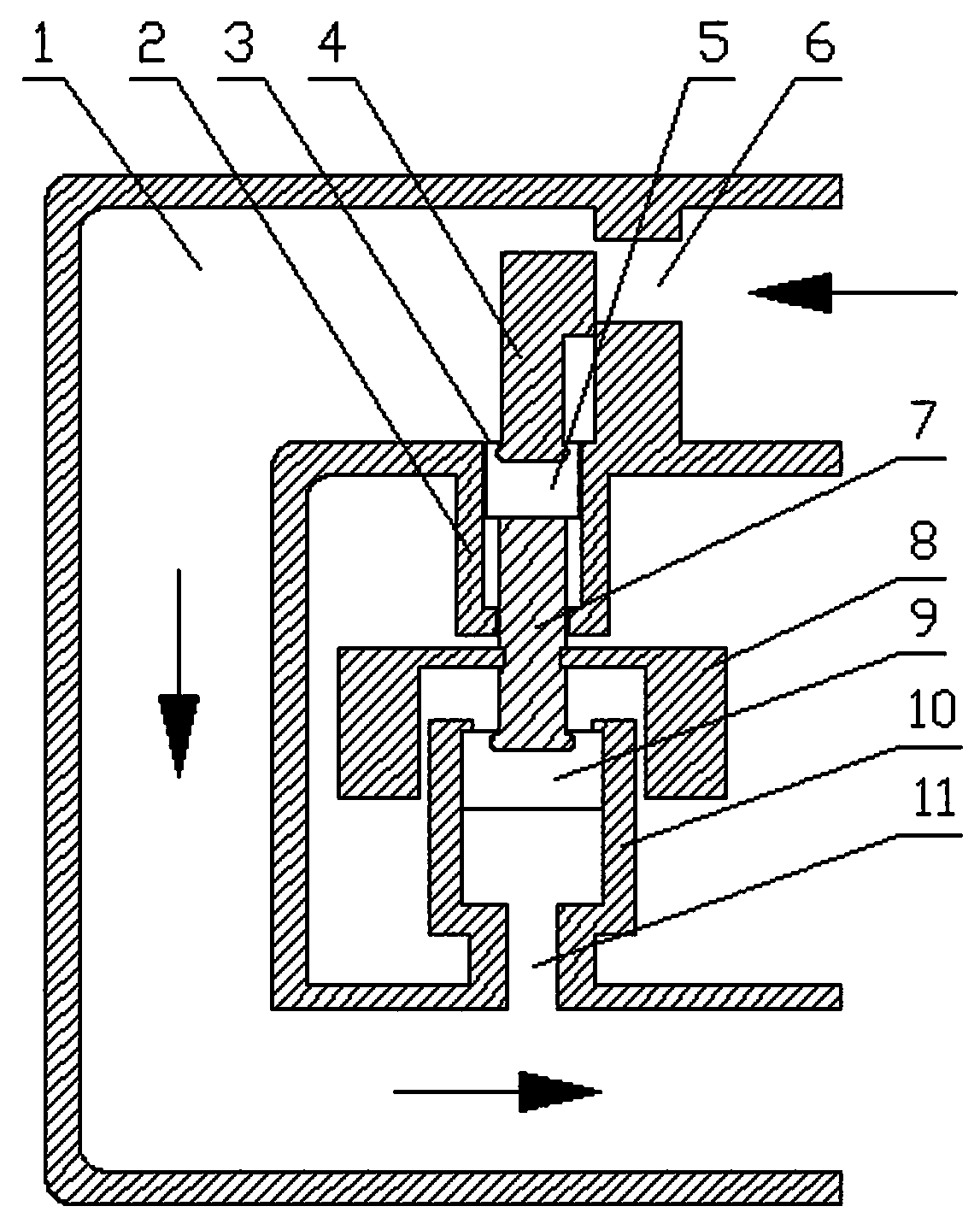
[0027] refer to figure 1 , the pipeline pressure (injection pressure) behind the oil pressure valve (i.e. flow control valve) is induced in two hydraulic cylinders at the same time, and the pressure generated in the two hydraulic cylinders acts on two different cross-sectional areas (S 1 , S 2 , S 1 2 ) size of the piston, the forces generated are PS 1 、PS 2 , since the pressure in the cylinder is the same, it is obvious that PS 1 2 , according to the above features, the two pistons and the control part 4 of the oil pressure valve have linkage to form a whole, then the whole will be moved due to uneven force, because the whole and the control part 4 of the oil pressure valve have linkage It will drive the opening and closing of the valve port 6 to change, and then the flow rate will change, and the change in the flow rate will in turn affect the injection pressure; when the gravity effect of the gravity loading part 8 is not loaded, due to the PS 1 always less than PS 2 ...

Embodiment 2

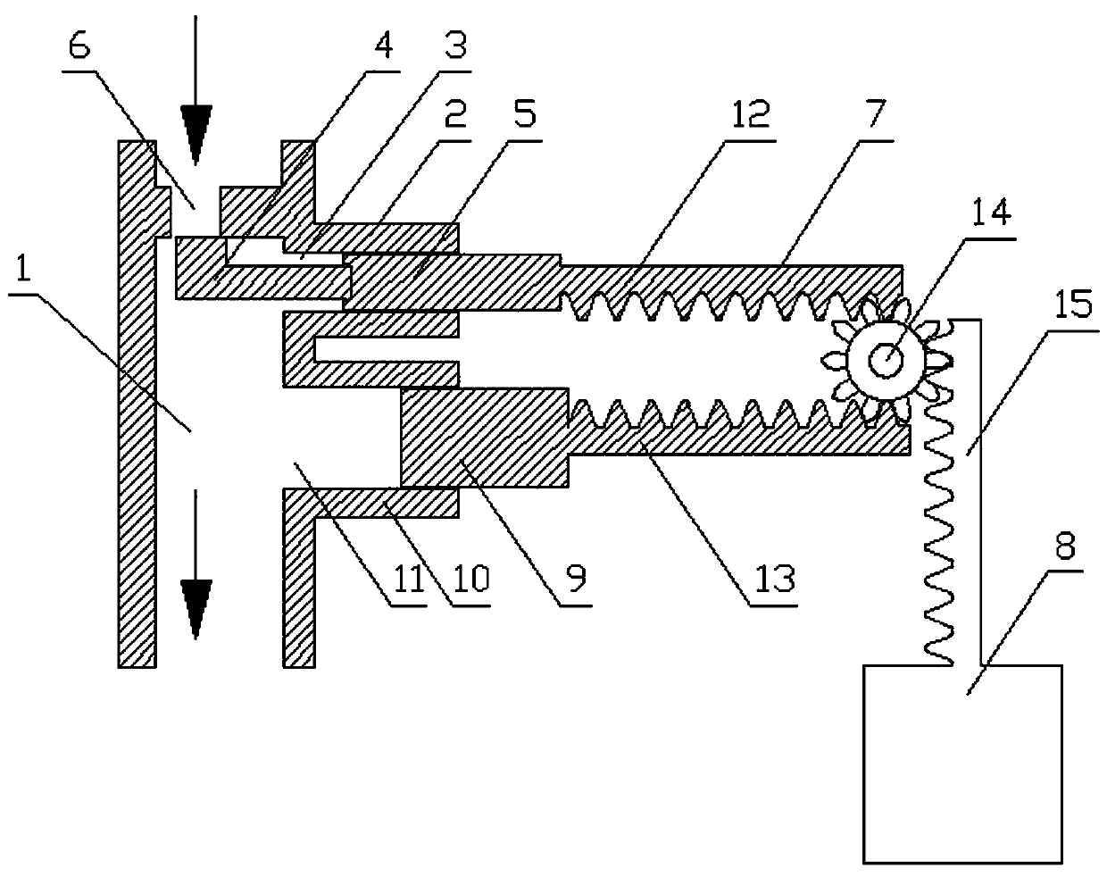
[0030] refer to figure 2 , the cross-sectional areas of the first piston 5 and the second piston 10 are respectively S 1 and S 2 , and S 1 less than S 2 , the meshing radius between the first rack 12 and the second rack 13 and the gear 14 is R 1 , the meshing radius between the third rack 15 and the gear 14 is R 2 , the positions of the third rack 15, the first rack 12 and the second rack 13 on the gear 14 are misaligned, and the forces generated on the first piston 5 and the second piston 10 are respectively PS 1 and PS 2 , and PS 1 less than PS 2 , the counterweight of gravity loading part 8 is G, PS 1 、PS 2 and G are transmitted to the gear 14 through the rack to generate torque on it, when PS 2 R 1 =PS 1 R 1 +GR 2 (Note: When G does not need to be enlarged, R 1 =R 2 , when it is necessary to amplify R 1 2 , simplified to R in the structure diagram 1 =R 2 When the situation), that is, P=GR 2 / (S 2 -S 1 ) R 1 , the overall force is balanced, then P is...


PUM


Abstract

The invention discloses an injection system used gravity to realize automatic adjustment of an oil field injection well and using method, and relates to the technical field of oil field equipment. Theinjection system used the gravity to realize automatic adjustment of the oil field injection well includes a flow duct, a valve port is arranged at the water inlet end of the flow duct, a first hydraulic cylinder and a second hydraulic cylinder are sequentially arranged on the flow duct according to the water flow direction, a first piston and a second piston are respectively mounted in the firsthydraulic cylinder and the second hydraulic cylinder, a first pressure guiding opening is formed between the first piston and the flow duct, a second pressure guiding opening is formed between the second piston and the flow duct, the first piston and the second piston are connected through a rigid connection object, the rigid connection object is provided with a gravity loading piece, the first piston is connected with an oil pressure valve through the control part of the oil pressure valve, and the oil pressure valve is matched with the valve port. According to the injection system used thegravity to realize automatic adjustment of the oil field injection well, injection pressure adjustment and injection volume control are automatically conducted, automatic control avoids artificial subjective factors affecting the injection effect, and the injection data are precise in time and exquisite in effect.

Description

Technical field: [0001] The invention relates to the technical field of oilfield equipment, in particular to an injection system and a use method for realizing automatic adjustment of oilfield injection wells by using gravity. Background technique: [0002] In the daily control and management of injection wells in oilfields, oil production engineers patrol the wells every day to control injection pressure (ie oil pressure) and injection volume according to the geological plan requirements, to ensure that the injection pressure (ie oil pressure) and injection volume are within the required range, control The equipment is an ordinary valve, most of which is a gate valve; the control method is: inspect the wellhead from the well, record the injection pressure (oil pressure) on site, if there is a deviation between the pressure value and the pressure value required by the plan, change the injection volume by switching the valve size To make the injection pressure (oil pressure) ...

Claims


Application Information

Patent Timeline
Patent Type & Authority Applications(China)
IPC IPC(8): E21B43/18
CPCE21B43/18
Inventor 胡升龙
Owner 江炎芬
Why Eureka
Try Eureka