
Metallurgy air separation oxygen supply pipe network system and operation method thereof

An operation method and technology of oxygen supply pipes, which are applied in the pipeline system, gas/liquid distribution and storage, mechanical equipment, etc., can solve the problem of high energy consumption and release loss of oxygen compression, the buffer potential of spherical tanks has not been fully utilized, Buffer capacity, oxygen release and other issues, achieve the effect of reducing the investment of spherical tanks, increasing the release range and buffer capacity, and realizing the pressure reduction of the pipe network

Active Publication Date: 2019-04-12
UNIV OF SCI & TECH BEIJING +1
View PDF4 Cites 6 Cited by
  • Summary
  • Abstract
  • Description
  • Claims
  • Application Information

AI Technical Summary

Problems solved by technology

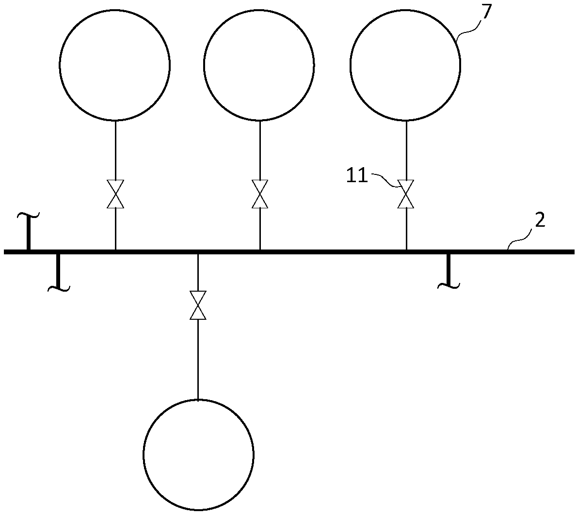
[0005] However, the operation of the existing oxygen supply network system has the following disadvantages: the buffer potential of the spherical tank has not been fully utilized
However, as far as the spherical tank itself is concerned, its pressure can vary between 0.1-3.0MPa in essence, that is, its potential release range limit is 2.9MPa
It can be seen that the buffer potential of the spherical tank has not been fully utilized
In addition, the pressure of the high-pressure pipe network on the industrial site generally does not approach the upper pressure limit of 3.0MPa to ensure its absolute safety. Usually, the oxygen is released at about 2.5MPa. At this time, the release range of the spherical tank is only 0.7MPa, and its buffer capacity is further improved. weaken
[0006] In metallurgical enterprises, the phenomenon of excessive pipe network pressure and oxygen release caused by insufficient buffer capacity of the oxygen supply pipe network system is still common, resulting in high energy consumption and release loss of oxygen compression.

Method used


Image

  • Metallurgy air separation oxygen supply pipe network system and operation method thereof
  • Metallurgy air separation oxygen supply pipe network system and operation method thereof
  • Metallurgy air separation oxygen supply pipe network system and operation method thereof

Examples


Embodiment 1

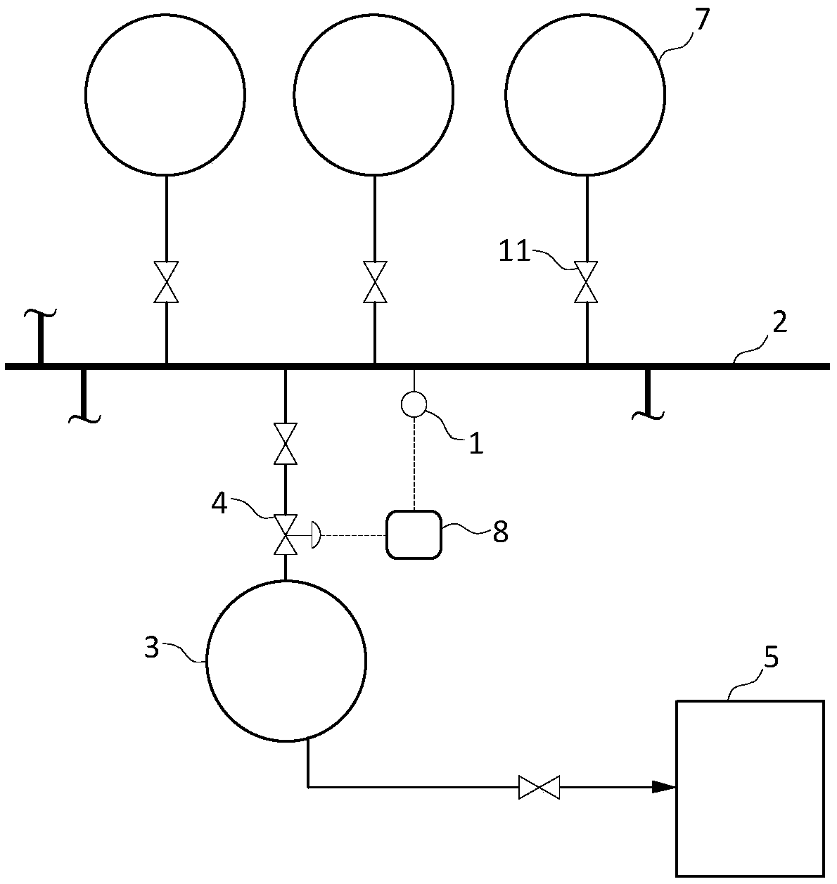
[0033] Such as figure 2 Shown is a partial flow chart of the oxygen supply pipeline network system in Embodiment 1. The first step of implementation is: select one or more spherical tanks in the oxygen supply network system as the first spherical tank 3, and then build a spherical tank control system according to the requirements of the operation method provided by the present invention. Such as figure 2 As shown, the specific construction method is: add a special valve-4 between the first spherical tank 3 and the high-pressure pipe network 2, and at the same time add an air supply pipeline between the first spherical tank 3 and the low-pressure user 5, and install a valve in the high-pressure pipe network. A pressure sensor 1 is set on the network 2, a signal connection line is set between the sensor and the controller 8, and a signal connection line is set between the controller 8 and the valve one 4, thereby forming a spherical tank control system. When there are multip...

Embodiment 2

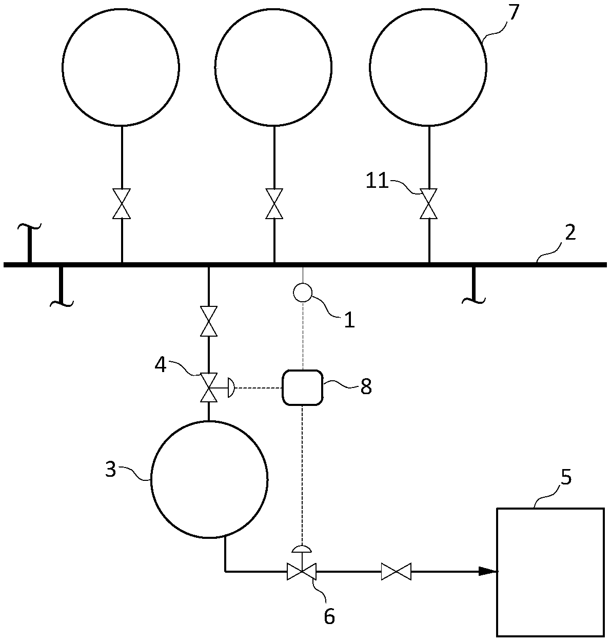
[0036] Such as image 3 Shown is a partial flow chart of the oxygen supply pipe network system in Embodiment 2 of the present invention. The first step of implementation is to select one or more spherical tanks in the oxygen supply network system as the first spherical tank, and then construct a spherical tank control system according to the requirements of the operation method provided by the present invention. Such as image 3 As shown, the specific construction method is as follows: a special valve 4 is added between the first spherical tank 3 and the high-pressure pipe network 2, and an air supply pipeline is added between the first spherical tank 3 and the low-pressure user 5, and the air supply Valve two 6 is set on the pipeline; pressure sensor 1 is set on the high-pressure pipe network 2, and a signal connection line is set between the sensor and the controller 8, between the controller 8 and the valve one 4, and between the controller 8 and the valve two 6 Signal co...

example 1

[0041] The total output of an air separation plant in a steel company in my country is 150,000Nm 3 / h, there are 5 sets of 1000m in the oxygen supply pipe network system 3 Oxygen spherical tanks, all of which are connected to the high-pressure pipe network. According to the production data of 30 days of normal production, the maximum pressure of the high-pressure pipe network is 2.54MPa, the minimum pressure is 1.82MPa, and the average pressure is 2.32MPa. The oxygen pressure of the blast furnace is 0.5MPa, and the average oxygen release rate is 2.43%. According to the calculation, the release range of the spherical tank is 0.72MPa, and the total buffer capacity of all spherical tanks is 36000m 3 , The buffer capacity is about the total output of the air separation unit for 15 minutes.

[0042] According to air separation output, pressure fluctuation, spherical tank volume and blast furnace oxygen consumption, etc., 3 tanks were transformed into the first spherical tank, and...


PUM


Abstract

The invention provides a metallurgy air separation oxygen supply pipe network system and an operation method thereof, and belongs to the technical field of metallurgy air separation energy conservation and consumption reduction. The metallurgy air separation oxygen supply pipe network system comprises a high-pressure pipe network and at least one first spherical tank, wherein a communication pipeline is arranged between the first spherical tank and the high-pressure pipe network; a valve is arranged on the communication pipeline; and during operation, an air supply pipeline is arranged betweenthe first spherical tank and a low-pressure user, the opening of the valve is adjusted according to pressure of the high-pressure pipe network, pressure of the high-pressure pipe network is between apressure upper limit and a pressure lower limit A, pressure of the first spherical tank is between the pressure upper limit and a pressure lower limit B, and the pressure lower limit B is smaller than the pressure lower limit A. According to the metallurgy air separation oxygen supply pipe network system and the operation method thereof, the communication state of the spherical tank and the high-pressure pipe network is controlled, the release range of the spherical tank is expanded, buffer capacity of the spherical tank is improved, depressurization and oxygen reduction of the high-pressurepipe network are achieved, and electricity of a metallurgy industry oxygen plant can be saved by 2.48% to 3.76%.

Description

technical field [0001] The invention relates to the technical field of metallurgical air separation energy saving and consumption reduction, in particular to a metallurgical air separation oxygen supply pipe network system and an operating method thereof. Background technique [0002] The oxygen supply pipe network system is an essential energy medium delivery system for metallurgical enterprises. The metallurgical process of iron and steel needs to consume a large amount of high-purity oxygen, which is mainly used in blast furnace ironmaking and converter steelmaking. Due to the huge amount of oxygen used in the iron and steel metallurgical process, metallurgical enterprises in my country generally have self-provided oxygen plants. There are generally several air separation units in the plant, and the high-purity oxygen produced by them is transported to various oxygen plants throughout the enterprise through the oxygen supply pipe network system. user. Different oxygen us...

Claims


Application Information

Patent Timeline
IPC IPC(8): F17D1/04F17D3/01
CPCF17D1/04F17D3/01
Inventor 张培昆王立凌晨牛子洋陈恩军吴冰
Owner UNIV OF SCI & TECH BEIJING
Learn More