
Jet-flow motion measuring device in scale model based on PIV

A scale model and motion measurement technology, applied in the field of laser measurement, can solve the problems of costing a lot of money, manpower and time, without considering the interference of hot plumes on cold jets, and damage to stratified air conditioning, etc., to achieve time-consuming and Low labor costs, improved indoor environmental quality, and optimized airflow organization

Pending Publication Date: 2019-04-12
UNIV OF SHANGHAI FOR SCI & TECH
View PDF10 Cites 9 Cited by
  • Summary
  • Abstract
  • Description
  • Claims
  • Application Information

AI Technical Summary

Problems solved by technology

Since the PIV measurement process has certain requirements on the light intensity, thickness and the permeability of the optical path, the existing indoor flow field measurement based on PIV technology is still subject to certain limitations. However, this measurement cannot meet the required flow field measurement range, which greatly limits the practical application of this technology.
The existing technology uses multiple cameras to measure at the same time, which requires a lot of money, manpower and time
Due to the lack of large-scale measured data and theoretical basis, the actual engineering design generally only uses the jet temperature difference as the basis, and simply applies the semi-empirical jet flow formula to carry out the design and calculation of the non-isothermal air supply airflow organization, without considering the effect of the hot plume on the cold jet. Interference effect, resulting in the layered layer of the actual layered air conditioner being damaged by the thermal plume, increasing the energy consumption of the air conditioner, and the design effect is not ideal

Method used


Image

  • Jet-flow motion measuring device in scale model based on PIV
  • Jet-flow motion measuring device in scale model based on PIV
  • Jet-flow motion measuring device in scale model based on PIV

Examples


Embodiment Construction

[0030] The following describes the preferred embodiments of the present invention with reference to the accompanying drawings to make the technical content clearer and easier to understand. The present invention can be embodied in many different forms of embodiments, and the protection scope of the present invention is not limited to the embodiments mentioned herein.

[0031] In the drawings, components with the same structure are denoted by the same numerals, and components with similar structures or functions are denoted by similar numerals. The size and thickness of each component shown in the drawings are shown arbitrarily, and the present invention does not limit the size and thickness of each component. In order to make the illustration clearer, the thickness of parts is appropriately exaggerated in some places in the drawings.

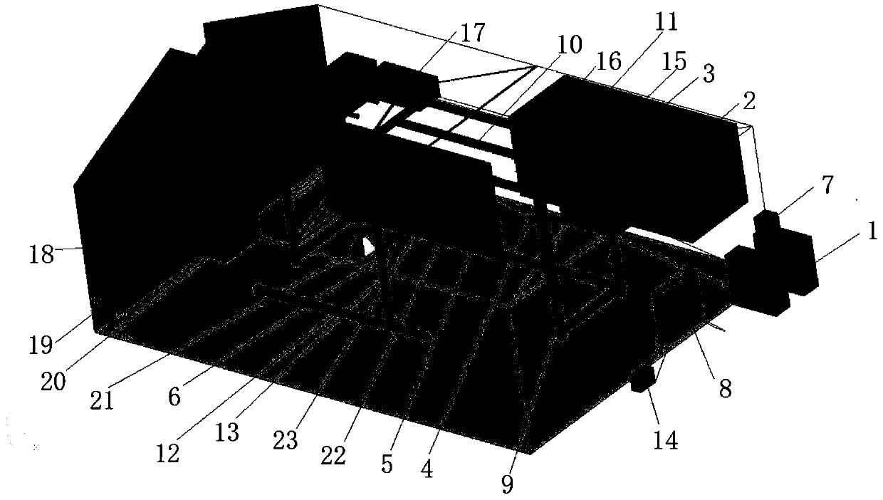
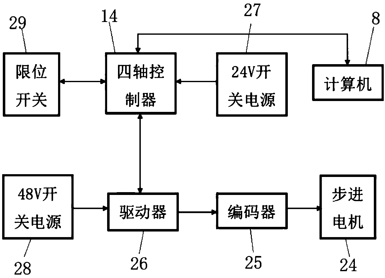
[0032] like figure 1 and figure 2 As shown, the present invention proposes a jet motion measurement device based on a PIV scale model, incl...


PUM


Abstract

The invention discloses a jet-flow motion measuring device in a scale model based on PIV, and relates to the technical field of laser measurement. The jet-flow motion measuring device in the scale model based on the PIV includes a laser light source system, a synchronous control system, a flow field imaging system, a particle image processing and analysis system, a movable sliding table system, atracer particle generator, a computer and a scale model; and the movable sliding table system includes a camera horizontal sliding table, a camera vertical sliding table, a laser device horizontal sliding table, a laser device vertical sliding table, a proximate matter frame, a transmission system and a sliding table automatic control system. Through the implementation of the jet-flow motion measuring device in the scale model based on the PIV, the limitation that an existing PIV testing technology has a small single measurement range is overcome, continuously measuring in the whole measuringarea can be carried out successively, the overall time-averaged flow information of the measuring area can be acquired, and the application scope of the PIV technology is greatly expanded.

Description

technical field [0001] The invention relates to the technical field of laser measurement, in particular to a jet movement measurement device in a scaled-down model based on PIV. Background technique [0002] With the rapid development of science and technology and the continuous improvement of social and economic levels, people's requirements for the comfort of the indoor thermal environment of large-space buildings are becoming more and more stringent. The airflow organization mode of horizontal jet nozzle side delivery is the air supply mode commonly used in large-space buildings at the present stage, which can not only ensure that the working area in the lower part of the building meets the air conditioning design requirements, but also achieves the purpose of energy saving. However, due to the lack of large-scale measured data and theoretical basis, the actual engineering design is generally based on the temperature difference of the jet flow, and the semi-empirical jet ...

Claims


Application Information

Patent Timeline
Patent Type & Authority Applications(China)
IPC IPC(8): G01M9/08
CPCG01M9/08
Inventor 王昕堵光耀许宇坤姜昕张玉洁施晨露朱卓邵明磊宋冰岩史云
Owner UNIV OF SHANGHAI FOR SCI & TECH
Learn More