
Quadruplicated frequency injection locking photoelectric oscillator

An optoelectronic oscillator and injection locking technology, applied in solid-state lasers and other directions, can solve the problems of poor output frequency stability, high implementation cost, and reduce phase noise, and achieve low-frequency stable output, low cost, and simple structure.

Active Publication Date: 2019-04-12
NANJING UNIV OF AERONAUTICS & ASTRONAUTICS
View PDF5 Cites 13 Cited by
  • Summary
  • Abstract
  • Description
  • Claims
  • Application Information

AI Technical Summary

Problems solved by technology

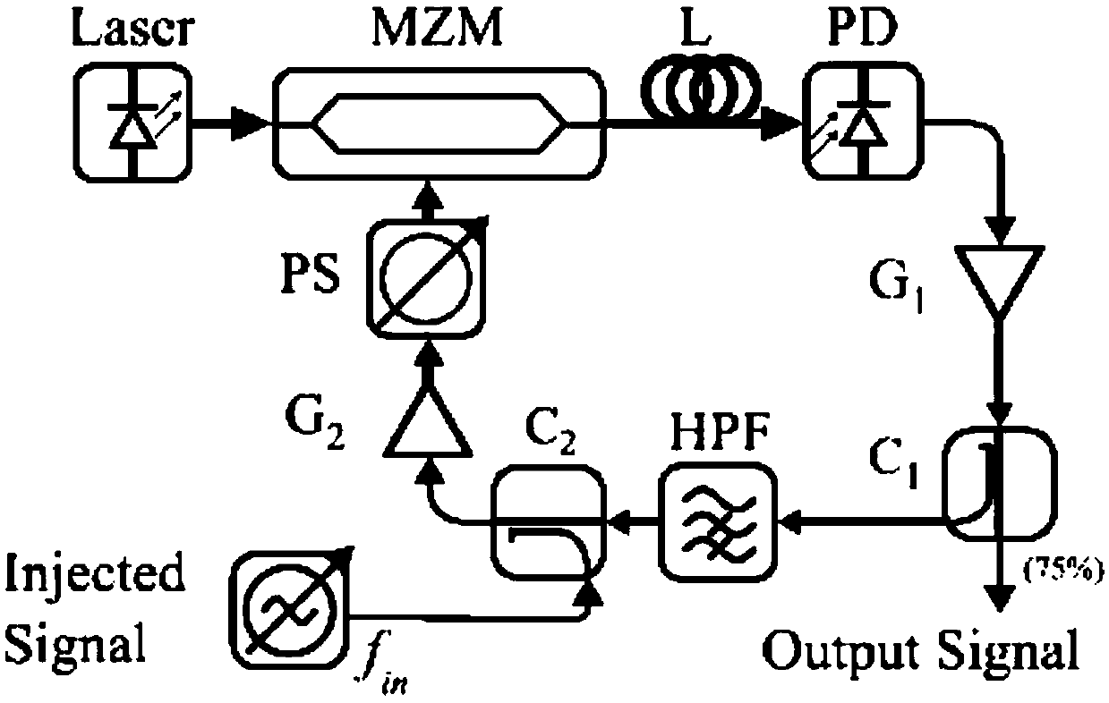
[0004] Since then, the development of optoelectronic oscillators has been particularly rapid. Among them, Weimin Zhou et al. proposed an injection-locked scheme using two opto-electronic oscillators [Weimin Zhou, Gregory Blasche. Injection-locked dual opto-electronic oscillator with ultra-low phase noise and ultra-low spurious level[J].IEEE Trans.on Microwave Theory and Techniques,2005,53(3):929~933.], improved double-loop structure can not effectively use long cavity to reduce phase noise while suppressing side modes However, the system structure of this scheme is relatively complicated, the cost is twice that of ordinary photoelectric oscillators, and the system volume is also large, and the temperature control is more difficult, resulting in poor stability of the output frequency; there is also injection locking to the external electrical oscillator [Fleyer M, Sherman A, Horowitz M, et al. Wideband-frequency tunable optoelectronic oscillator based on injection locking to an electronic oscillator [J]. Optics Letters, 2016, 41(9): 1993.], such as figure 1 As shown, although the side mode can be effectively suppressed due to the influence of injection, the quality of the injected signal is high, and the frequency of the injected and output signals is required to be the same, the structure is complex, and the cost of implementation is high.

Method used


Image

  • Quadruplicated frequency injection locking photoelectric oscillator
  • Quadruplicated frequency injection locking photoelectric oscillator
  • Quadruplicated frequency injection locking photoelectric oscillator

Examples


Embodiment Construction

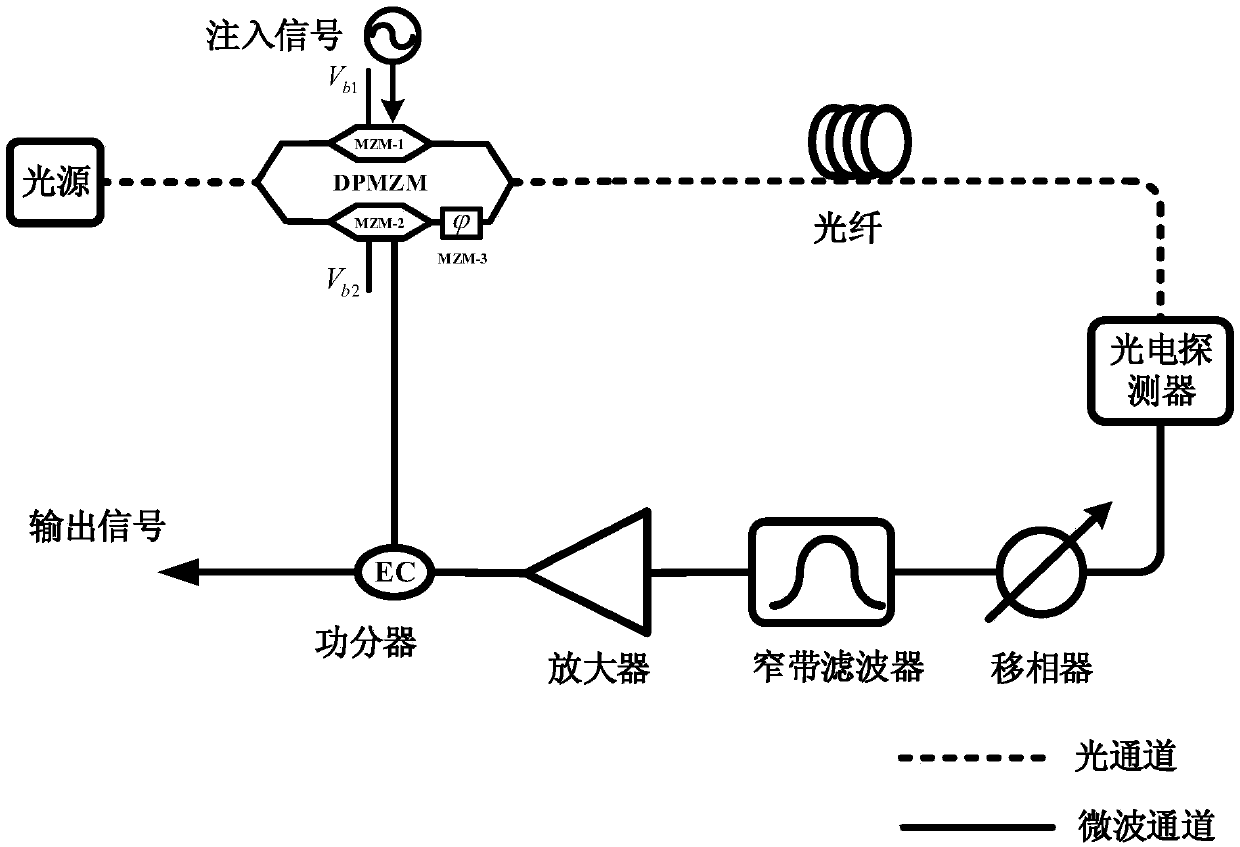
[0022] Aiming at the deficiencies in the prior art, the idea of ​​the present invention is to use a dual-parallel Mach-Zehnder modulator (DPMZM, Dual-parallel Mach-Zehnder modulator) to construct an optoelectronic oscillator, by generating a quadruple frequency mode in the optoelectronic loop Positive feedback oscillation, on the one hand, realizes high-quality and stable output of microwave signals whose frequency is four times that of the injected signal, and on the other hand, greatly simplifies the system structure and reduces the cost of system implementation. Due to the unique dual-parallel MZM structure of DPMZM, it can be used not only as an external injection unit but also as an oscillation feedback loop terminal. Such as figure 2 As shown, the quadruple frequency injection-locked optoelectronic oscillator of the present invention includes: a light source, a DPMZM, an optical fiber delay line, a photodetector, a phase shifter, a microwave bandpass filter, a microwave...


PUM


Abstract

The invention discloses a quadruplicated frequency injection locking photoelectric oscillator. The quadruplicated frequency injection locking photoelectric oscillator comprises a dual-parallel mach-zehnder modulator (DPMZM), a light source, a photoelectric detector, a phase shifter, a microwave filter, a microwave amplifier and a power divider, wherein one radio frequency input port of the DPMZM is connected with a single-frequency injection signal, the light source is used for providing a light carrier for the DPMZM, an input end of the photoelectric detector is connected with an output end of the DPMZM by a fiber delay line, the phase shifter is used for adjusting a phase of an electrical signal, the microwave filter is used for filtering the electrical signal and is a narrow-band filterof which passband is around a quadruplicated frequency of the single-frequency injection signal, the microwave amplifier is used for amplifying the electrical signal, the power divider is used for dividing the electrical signal into two paths after the phase shifter, the microwave filter and the microwave amplifier, one path is input to the other radio frequency input port of the DPMZM, and the other path is used as an oscillation signal output of the quadruplicated frequency of the single-frequency injection signal. By the quadruplicated frequency injection locking photoelectric oscillator,stable output of the quadruplicated frequency of the injection signal can be achieved, and the quadruplicated frequency injection locking photoelectric oscillator is simple in structure and low in implementation cost.

Description

technical field [0001] The present invention relates to an optoelectronic oscillator (OEO for short), in particular to a quadruple frequency injection-locked optoelectronic oscillator. Background technique [0002] In the 1990s, with the rapid development of communication and information industries, human beings have officially entered the information society, and massive information transmission and processing will become the inevitable direction of scientific and technological progress. At the same time, human beings have higher and higher expectations for communication quality and accuracy. In order to meet the needs of high-speed communication and broadband communication, human beings have stricter requirements on the frequency and quality of electromagnetic waves. However, the spectral purity of the microwave and millimeter waves generated by traditional high-speed oscillations has been difficult to meet the needs of future communications. Almost all traditional high-...

Claims


Application Information

Patent Timeline
Patent Type & Authority Applications(China)
IPC IPC(8): H01S1/02
CPCH01S1/02
Inventor 潘时龙吕凯林刘世锋康晓晨刘鸿飞傅剑斌
Owner NANJING UNIV OF AERONAUTICS & ASTRONAUTICS
Learn More