Supercharge Your Innovation With Domain-Expert AI Agents!

Capacitance clamping-based three-phase interleaving ultrahigh-gain boost converter

A boost converter and capacitor clamping technology, which is applied in the direction of adjusting electric variables, output power conversion devices, DC power input conversion to DC power output, etc., can solve high current peaks, large current ripples, and low voltage gain etc. to achieve the effects of high voltage gain, low voltage stress, and low input current ripple

Active Publication Date: 2019-04-12
BEIJING JIAOTONG UNIV
View PDF6 Cites 2 Cited by
  • Summary
  • Abstract
  • Description
  • Claims
  • Application Information

AI Technical Summary

Problems solved by technology

For switched capacitor high-gain converters, it can achieve higher voltage gain, but it will cause higher current peaks due to capacitor charging and discharging during switching, which will affect the efficiency and reliability of the converter; Due to the parallel charging and series discharging of the input side inductors of the high-gain converter, the current ripple on the input side is relatively large, which affects the life of the battery
[0004] For problem 2, currently the interleaved parallel structure is mainly used to reduce the current ripple on the input side, but generally the voltage gain is relatively low
For example, one of the most basic two-phase interleaved parallel Boost converters in related technology is formed by interleaving and paralleling two traditional Boost converters, which can reduce the input current ripple of the converter, but does not increase the voltage gain of the converter
In order to increase the voltage gain of the converter, another related technology proposes a two-phase interleaved parallel boost converter, which adds a voltage doubler module on the basis of the traditional two-phase interleaved parallel Boost converter to double the output voltage, but the structure More complicated, the voltage doubler module includes two capacitors and two diodes, and the voltage gain is only doubled

Method used


Image

  • Capacitance clamping-based three-phase interleaving ultrahigh-gain boost converter
  • Capacitance clamping-based three-phase interleaving ultrahigh-gain boost converter
  • Capacitance clamping-based three-phase interleaving ultrahigh-gain boost converter

Examples


Embodiment Construction

[0039] Embodiments of the present invention are described in detail below, examples of which are shown in the drawings, wherein the same or similar reference numerals designate the same or similar elements or elements having the same or similar functions throughout. The embodiments described below by referring to the figures are exemplary and are intended to explain the present invention and should not be construed as limiting the present invention.

[0040] The following describes the three-phase interleaved parallel ultra-high gain boost converter based on capacitance clamping according to the embodiments of the present invention with reference to the accompanying drawings.

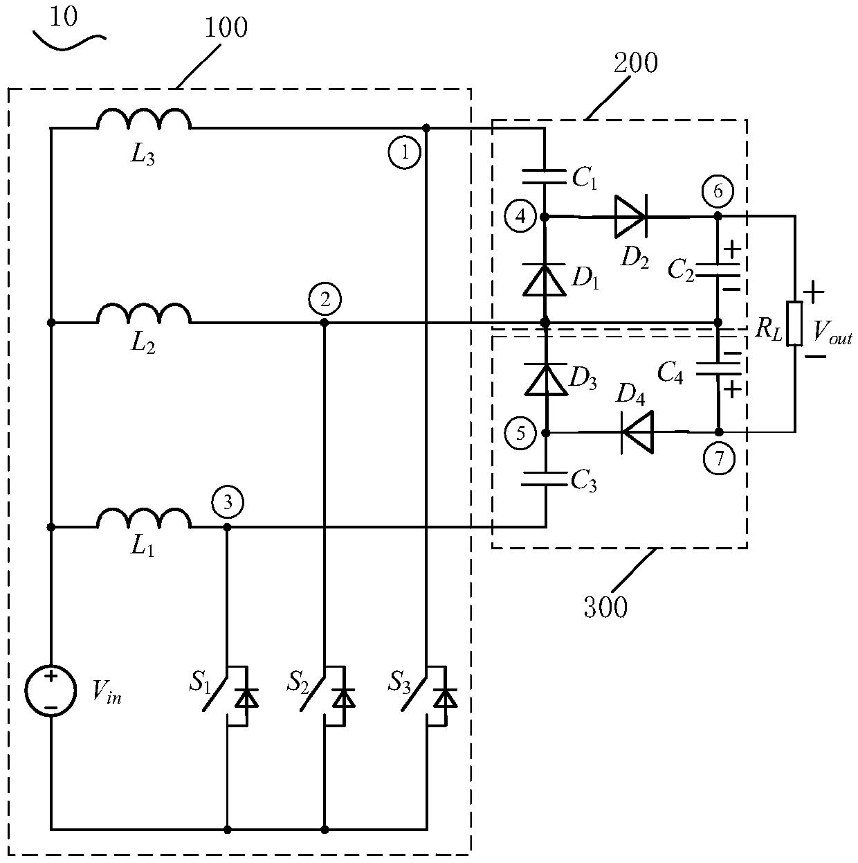
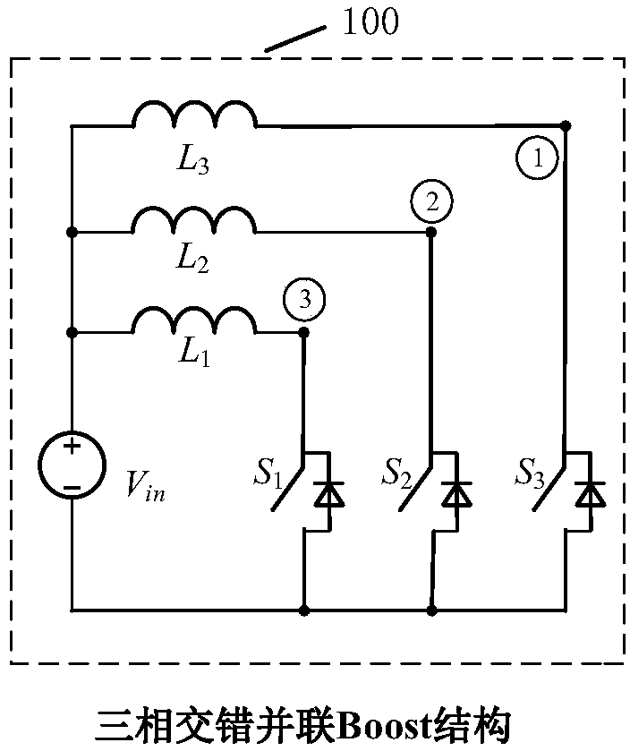
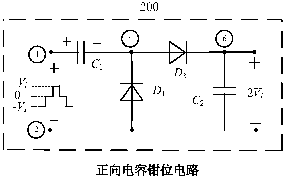
[0041] figure 1 It is a structural schematic diagram of a three-phase interleaved parallel ultra-high gain boost converter based on capacitance clamping according to an embodiment of the present invention.

[0042] Such as figure 1 As shown, the capacitor clamp-based three-phase interleaved parallel u...


PUM


Abstract

The invention discloses a capacitance clamping-based three-phase interleaving ultrahigh-gain boost converter. The capacitance clamping-based three-phase interleaving ultrahigh-gain boost converter comprises a load, a positive capacitance clamping circuit, a reverse capacitance clamping circuit and a three-phase interleaving Boost structure, wherein positive capacitance clamping circuit comprises afirst capacitor, a second capacitor, a first diode and a second diode, the reverse capacitance clamping circuit comprises a third capacitor, a fourth capacitor, a third diode and a fourth diode, thethree-phase interleaving Boost structure comprises a first inductor, a second inductor, a third inductor, a first switch tube, a second switch tube, a third switch tube and an input source, the three-phase interleaving Boost structure is connected with the positive capacitance clamping circuit by a first node and a second node and is connected with the reverse capacitance clamping circuit by the second node and a third node, and the load is connected with the positive capacitance clamping circuit and the negative capacitance clamping circuit by a sixth node and a seventh node. The converter has the characteristics of ultrahigh voltage gain, ultralow input current ripple and low voltage stress and is applicable to the field of grid-connected power generation of a fuel cell and a photovoltaic cell.

Description

technical field [0001] The invention relates to the technical field of power electronics, in particular to a three-phase interleaved parallel ultra-high gain boost converter based on capacitance clamping. Background technique [0002] Due to the increasing environmental pollution and the depletion of petroleum resources, clean and pollution-free renewable energy power generation technologies are favored, such as fuel cells and photovoltaic cells. However, there are two problems in the power generation technology of fuel cells and photovoltaic cells. One is that the output voltage of fuel cells and photovoltaic cells is relatively low, generally only 20-50V, while the DC bus voltage of the grid-connected inverter is 400V / 750V. The high-gain converter converts 20-50V into a DC voltage of 400V / 750V; the second is that fuel cells and photovoltaic cells are more sensitive to current ripples, and larger current ripples will reduce the life of fuel cells and photovoltaic cells. Th...

Claims


Application Information

Patent Timeline
IPC IPC(8): H02M3/158
CPCH02M3/1584Y02E10/56
Inventor 李虹曾洋斌王文财张波吕金虎郑琼林
Owner BEIJING JIAOTONG UNIV
Features
  • R&D
  • Intellectual Property
  • Life Sciences
  • Materials
  • Tech Scout
  • Unparalleled Data Quality
  • Higher Quality Content
  • 60% Fewer Hallucinations
Learn More