Asphalt VOCs waste gas purification device

A technology of asphalt and dust removal device, applied in external electrostatic separator, electrostatic separation, electrode cleaning, etc., can solve the problems of low purification efficiency, difficult to clean the electrode plate, polluted exhaust gas, etc.

Pending Publication Date: 2019-04-16
ZHEJIANG ISUAO ENVIRONMENTAL TECH CO LTD
View PDF2 Cites 2 Cited by
  • Summary
  • Abstract
  • Description
  • Claims
  • Application Information

AI Technical Summary

Problems solved by technology

At present, most of the asphalt mixing tanks and raw material storage tanks are heated by heating the heat transfer oil in the boiler. The boiler heating process will produce a certain amount of polluted exhaust gas, and the temperature at the boiler exhaust port can reach 400 ° C. The heat loss is relatively large.
At present, the main methods to solve asphalt fume purification are: mechanical collision, activated carbon filter, electrostatic adsorption and combustion methods, etc. Although they can reduce asphalt fume to a certain extent, they are not thorough, and environmental pollution still has the following problems : 1. For the mechanical collision type, the wind resistance is large, the purification efficiency is low, and it cannot remove tiny particles, odors and harmful gases; 2. For the activated carbon filter type, it is easy to be saturated, the replacement cycle is short, and the loss rate is low. and cost increase; 3. For the electrostatic adsorption method, the smoke particles are purely adsorbed and efficiently captured by charging the smoke particles. However, in practical applications, the plates are difficult to clean, and cannot effectively remove odors and cannot degrade flue gas. Molecule and other disadvantages
4. High operating costs for the combustion method

Method used


Image

  • Asphalt VOCs waste gas purification device

Examples


Embodiment Construction

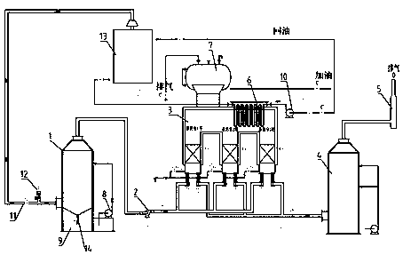
[0011] see figure 1 , connect the air inlet of the 1-high-voltage electrostatic precipitator to the collection cover of the asphalt mixing tank through the SUS304 air pipe, and set a cut-off valve and a fresh air valve on the connecting pipes respectively. When the cut-off valve is cut off, the exhaust gas will not enter the treatment At the same time, the fresh air valve will automatically open, and the fresh air supplied by the fresh air valve can ensure the normal temperature rise or operation of the regenerative combustion and heat transfer oil heat exchange device. Connect the air outlet of 1-high-voltage electrostatic dust removal device and the air inlet of 3-regenerative combustion and heat transfer oil heat exchange device through pipelines, and install induced draft fans on the connecting pipelines. Connect the air outlet of the 3-regenerative combustion and heat transfer oil heat exchange device with the air inlet of the 4-desulfurization tower device through pipes....


PUM


Abstract

The invention aims to provide an asphalt VOCs waste gas purification device which is used for the waste gas treatment of an asphalt production workshop, and the heat exchange of the heat conduction oil in heat equipment in the asphalt production workshop. The device comprises a high-voltage electrostatic dust removal device, an induced draft fan, a heat accumulating type combustion and heat conduction oil heat exchange device, a desulfurization tower and a chimney. The device has the following advantages: the smell of the VOCs waste gas in the asphalt, and oily and viscous substances in the smoke of the asphalt can be thoroughly and effectively removed. Meanwhile, the device is combined with a conduction oil heat exchanger. The heat transfer oil in the production process is subjected to heat exchange by using the hearth heat of a heat accumulating type combustion device. Due to the fact that the heat exchange efficiency of a regenerative chamber combustion device can reach 95% or above, the problem of waste gas purification is solved. Meanwhile, the use of the boiler in the asphalt production process can be reduced. The purposes of saving energy consumption and achieving clean production are achieved.

Description

technical field [0001] The invention relates to the field of asphalt flue gas treatment and the heating of asphalt raw material storage tanks and mixing tanks, in particular to an asphalt VOCs waste gas purification device. Background technique [0002] The asphalt fume emitted during asphalt processing and production is usually mixed with dust, low molecular oil fumes and other substances, causing environmental pollution. At the same time, in the production process of asphalt, the asphalt mixing tank and raw material storage tank need to be heated by heat transfer oil. At present, most of the asphalt mixing tanks and raw material storage tanks are heated by boilers heating heat transfer oil. The boiler heating process will produce a certain amount of polluted exhaust gas, and the temperature at the boiler exhaust port can reach 400 ° C. The heat loss is relatively large. At present, the main methods to solve asphalt fume purification are: mechanical collision, activated ca...

Claims


Application Information

Patent Timeline
IPC IPC(8): B03C3/04F23G7/06B03C3/78
CPCF23G7/06B03C3/04B03C3/78
Inventor 何国利邵建新邵方荣
Owner ZHEJIANG ISUAO ENVIRONMENTAL TECH CO LTD
Why Eureka
Try Eureka