Electrochemical ceramic membrane oxygen producing machine and oxygen producing equipment thereof

An oxygen-generating equipment and ceramic membrane technology, applied in the field of electrochemical ceramic membrane oxygen-generating machines and oxygen-generating equipment, can solve the problems of short service life, small oxygen-generating capacity, and many moving parts, etc., and save the use cost and structure. Simple and reliable, technically optimal results

Active Publication Date: 2019-04-16
北京汉华元生科技有限公司
View PDF8 Cites 5 Cited by
  • Summary
  • Abstract
  • Description
  • Claims
  • Application Information

AI Technical Summary

Problems solved by technology

Due to the low oxygen and nitrogen separation coefficient of the organic membrane, poor thermal stability, short service life, and easy to block, the purity of oxygen products is generally ≤45%, and the oxygen production capacity is small, which cannot meet the oxygen consumption requirements of the metallurgical industry and the three major chemical industries. quantity and quality of oxygen
[0006] The existing oxygen production technology cannot produce pure oxygen, high-purity oxygen and ultra-pure oxygen at the same time on site, and cannot meet the oxygen demand of various industries at the same time: cryogenic gas separation can only be realized in a low temperature environment below 100K, and the investment is large , only suitable for large-scale gas separation process, for medical and other small and medium-scale dispersed applications, the oxygen produced by cryogenic method needs to be packaged, distributed and stored, the fire protection requirements are high, and it cannot be produced and used on the spot; membrane separation Oxygen concentration of the products produced by the method is low (less than 45%), and the scale is only suitable for small and medium-sized. 96%, there are many moving parts, loud noise, regular maintenance is required, as the service life increases, the concentration pressure will attenuate, the failure rate will increase, and the use cost will be high

Method used


Image

  • Electrochemical ceramic membrane oxygen producing machine and oxygen producing equipment thereof
  • Electrochemical ceramic membrane oxygen producing machine and oxygen producing equipment thereof
  • Electrochemical ceramic membrane oxygen producing machine and oxygen producing equipment thereof

Examples


Embodiment Construction

[0028] The technical solutions in the embodiments of the present invention are clearly and completely described below in conjunction with the accompanying drawings in the embodiments of the present invention. Obviously, the described embodiments are part of the embodiments of the present invention, but not all of them. Based on the embodiments of the present invention, all other embodiments obtained by those skilled in the art without making creative efforts belong to the protection scope of the present invention.

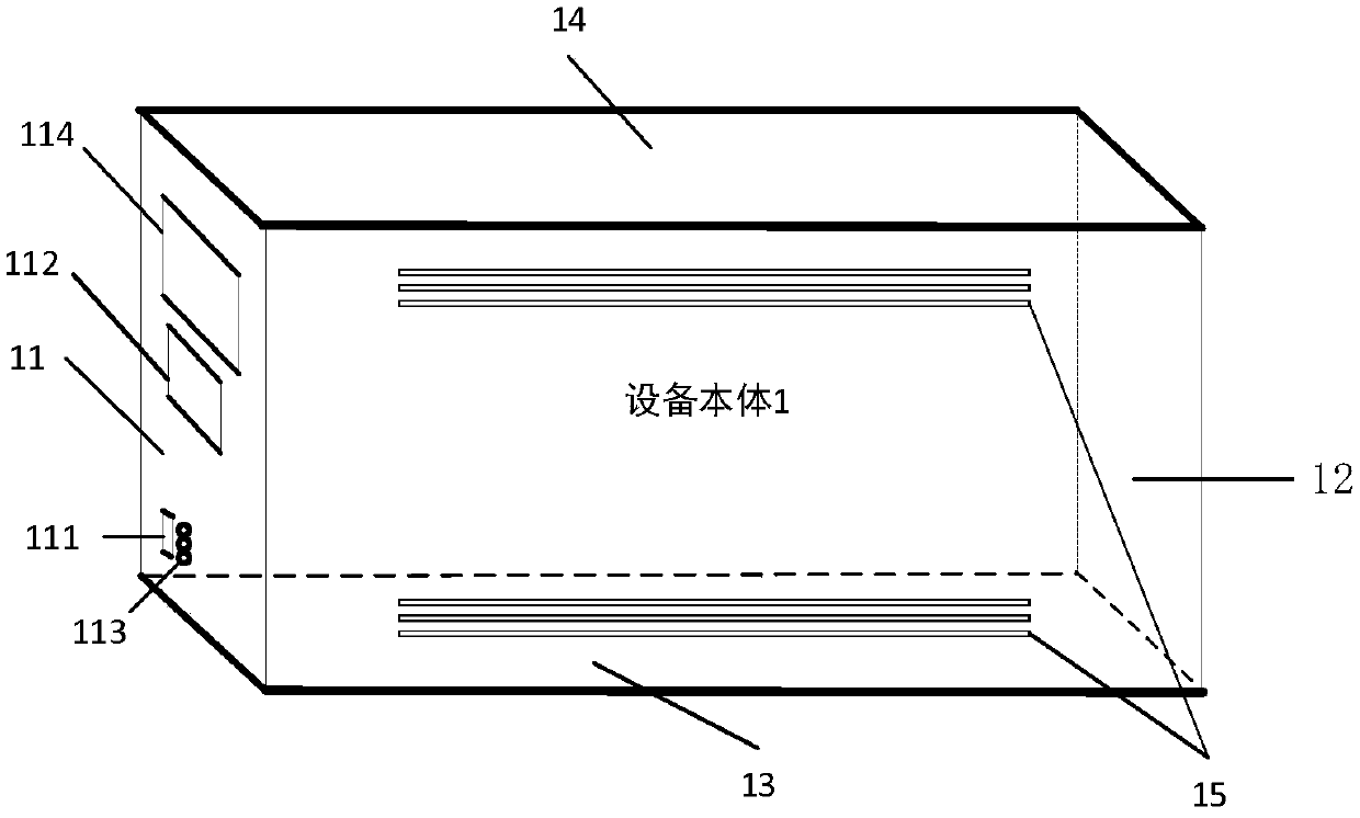
[0029] Such as figure 1 As shown, the embodiment of the present application provides an oxygen generator, which includes a device body 1, the device body 1 consists of a front panel 11, a rear panel 12, two parallel side panels (not shown), a bottom plate 13 and a cover plate 14 parallel to the bottom plate 13 surround a cuboid. On the front panel 11, a running switch 111, a control panel 112, an indicator light 113 and a display screen 114 are set, wherein the ru...


PUM


Abstract

The invention discloses an electrochemical ceramic membrane oxygen producing machine and oxygen producing equipment thereof, and relates to the technical field of oxygen production. The electrochemical ceramic membrane oxygen producing machine comprises a ceramic membrane stack, an airflow distributor, a heater, double helical exchangers and thermal isolation sleeves; the ceramic membrane stack comprises electrochemical ceramic membrane pieces vertically stacked parallelly, the sides of the electrochemical ceramic membrane pieces are closed to form vertical cavities, the other sides of the electrochemical ceramic membrane pieces are connected with oxygen outputting pipes through ceramic pipes, the bottom of the ceramic membrane stack closely fits the upper surface of the airflow distributor, and a heater is arranged at the lower end of the airflow distributor; the outer sides of the ceramic membrane stack, the airflow distributor and the heater are wrapped by the double helical exchangers, and the thermal isolation sleeves sleeve the two ends of each double helical exchanger and converge on a double helical interaction device. The electrochemical ceramic membrane oxygen producing machine and the oxygen producing equipment thereof can prepared pure oxygen, high-purity oxygen and hyperpure oxygen on site, and are small in size, light in weight, low in cost and suitable for quickdeployment.

Description

technical field [0001] The present application relates to the technical field of oxygen production, in particular to an electrochemical ceramic membrane oxygen generator and its oxygen production equipment. Background technique [0002] At present, oxygen is mainly obtained through separation, and there are three technical methods for air separation: cryogenic method, adsorption method, and organic membrane separation method. [0003] Cryogenic method: Utilizing the different boiling points of the components in the air, through a series of processes, the air is liquefied, and the different components are separated by rectification. This method can realize the complete separation of air components, product refinement, large-scale equipment, and dual state (liquid and gas), so the industrialization of the production equipment occupies a leading position. At present, the most widely used in industry is cryogenic air separation technology. The concentration of oxygen produced ...

Claims


Application Information

Patent Timeline
Patent Type & Authority Applications(China)
IPC IPC(8): C01B13/02B01D53/32
CPCB01D53/32B01D2256/12C01B13/0255C01B2210/0012
Inventor 陈国旗张立李晓王季柠
Owner 北京汉华元生科技有限公司
Why Eureka
Try Eureka