Supercharge Your Innovation With Domain-Expert AI Agents!

T-type distilled water machine separation system

A technology of distilled water machine and separation system, applied in water/sewage treatment, multi-stage water/sewage treatment, degassed water/sewage treatment, etc., can solve the problems of reduced cooling efficiency, waste of resources, increased power consumption, etc., to achieve Improve service life, improve production efficiency, and save resources

Active Publication Date: 2021-08-13
YANGZHOU TIANCHENG WATER TREATMENT EQUIP ENG CO LTD
View PDF0 Cites 0 Cited by
  • Summary
  • Abstract
  • Description
  • Claims
  • Application Information

AI Technical Summary

Problems solved by technology

[0003] However, the steam and raw water introduced before the distilled water machine work cannot be effectively treated, resulting in a low service life of the distilled water machine. It is mainly divided into the steam that is introduced due to the existence of condensable gas that is very harmful to the system. The main performance The condensation pressure of the system will increase, the condensation temperature will increase, the discharge temperature of the compressor will increase, the power consumption will increase, and the refrigeration efficiency will decrease; at the same time, due to the excessive discharge temperature, the lubricating oil may be carbonized, which will affect the lubrication effect. Burned out refrigeration compressor motor
However, there are effective substances in the raw water, such as phenols, benzene compounds that are harmful to health, and even evaporable mercury, etc., which are also condensed into the distilled water with the generation of distilled water, resulting in the resulting distilled water being not pure enough.
In addition, a large amount of heat needs to be dissipated in the separation system, which will cause heat loss and waste resources

Method used


Image

  • T-type distilled water machine separation system
  • T-type distilled water machine separation system
  • T-type distilled water machine separation system

Examples


Embodiment Construction

[0027] The following will clearly and completely describe the technical solutions in the embodiments of the present invention with reference to the accompanying drawings in the embodiments of the present invention. Obviously, the described embodiments are only some, not all, embodiments of the present invention. Based on the embodiments of the present invention, all other embodiments obtained by persons of ordinary skill in the art without creative efforts fall within the protection scope of the present invention.

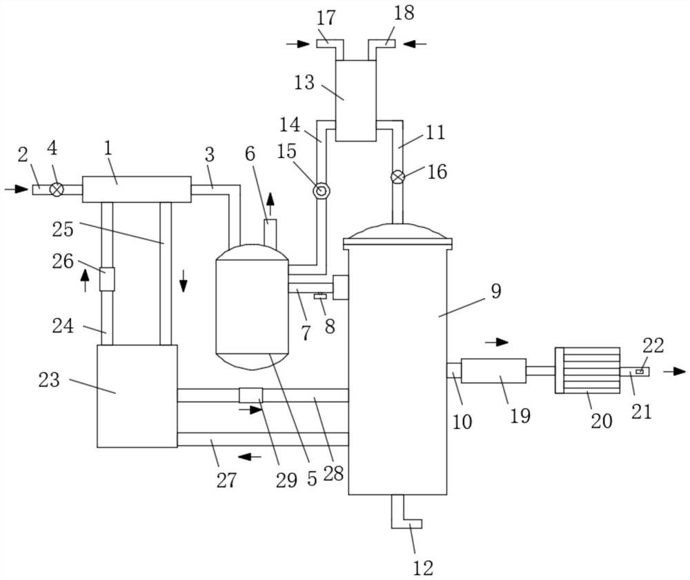
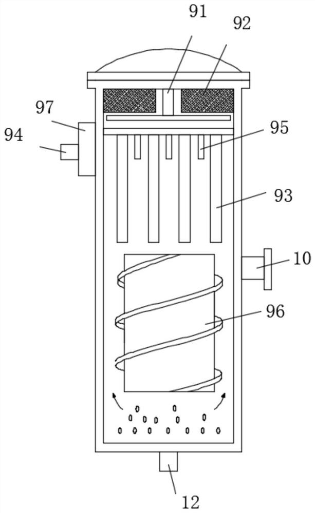
[0028] see Figure 1-3 , the present invention provides a technical solution: a T-type distilled water machine separation system, including a T-type distilled water machine separation unit, and also includes a raw water heating unit, a non-condensable gas separation unit, a distilled water treatment unit, a condensation unit and a heat recovery unit;

[0029] The raw water heating unit includes a raw water heater 1, a water supply pipe 2, a heating raw water pipe 3...


PUM


Abstract

The invention discloses a T-type distilled water machine separation system in the technical field of distilled water machines, which includes a T-type distilled water machine separation unit, and also includes a raw material water heating unit, a non-condensable gas separation unit, a distilled water treatment unit, a condensation unit and a heat recovery unit. The water heating unit includes raw water heater, water supply pipe, heating raw water pipe and water supply regulating valve, the non-condensable gas separation unit includes non-condensable gas separator, non-condensable gas discharge pipe, steam delivery pipe, pneumatic regulating valve and water inlet pipe, distilled water The processing unit includes water outlet pipe, distilled water buffer tank, water valve, feeding pipe 1 and feeding pipe 2, the condensing unit includes a primary condenser, a secondary condenser and a liquid discharge port, and the heat recovery unit includes a heat recovery device, a heat cycle Pipe 1, heat recovery pipe 1, heat recovery pipe 2 and heat circulation pipe 2, separate the raw water for many times, remove harmful substances and non-condensable gases in the raw water, ensure pure distilled water, and fully recover heat energy use.

Description

technical field [0001] The invention relates to the technical field of distilled water machines, in particular to a T-type distilled water machine separation system. Background technique [0002] Distilled water is widely used. In order to produce pure distilled water, T-type distilled water machine is generally used for processing. The working principle of distilled water machine: the production is to boil the source water and let it evaporate and condense for recovery. It will consume a lot of heat energy and the cost will not be too high. Low, other heat-evaporating substances in the source water used to make distilled water will condense into distilled water with the generation of distilled water, such as phenols, benzene compounds that are harmful to health, and even evaporable mercury. In order to obtain pure water or ultrapure water, it is necessary to undergo two or three distillations and to add other means of purification. [0003] However, the steam and raw water...

Claims


Application Information

Patent Timeline
Patent Type & Authority Patents(China)
IPC IPC(8): C02F9/10
CPCC02F1/04C02F1/20C02F1/58C02F1/586C02F1/62C02F9/00
Inventor 侯承洲刘伟倪梨阚礼平
Owner YANGZHOU TIANCHENG WATER TREATMENT EQUIP ENG CO LTD
Features
  • R&D
  • Intellectual Property
  • Life Sciences
  • Materials
  • Tech Scout
  • Unparalleled Data Quality
  • Higher Quality Content
  • 60% Fewer Hallucinations
Learn More