
Gravity energy storage system of hoisting and transporting system based on mine vertical shaft

A technology of transportation system and energy storage system, applied to lifting equipment, transportation and packaging, elevators and other directions in mines, can solve the problems of low total efficiency, high maintenance cost, high system complexity, and achieve long-term energy storage without loss , High energy cycle efficiency, overcoming the effect of low efficiency

Pending Publication Date: 2019-04-23
中煤能源研究院有限责任公司
View PDF1 Cites 11 Cited by
  • Summary
  • Abstract
  • Description
  • Claims
  • Application Information

AI Technical Summary

Problems solved by technology

However, this scheme occupies a large area of ​​useful land, has many geographical constraints, a large amount of engineering, and the overall efficiency is not high (about 80% for one-way, about 60% for two-way), and the maintenance cost is high, so the practical value is limited.
More skilled technicians may further imagine that braking is not performed in the first part of the glide stroke, but arresting cables are only installed in the straight section at the end of the sloped rail, and the kinetic energy is converted into electrical energy through the braking of the arresting cables, then the total efficiency can be obtained. Increased to about 70%, but with high system complexity

Method used


Image

  • Gravity energy storage system of hoisting and transporting system based on mine vertical shaft

Examples


Embodiment 1

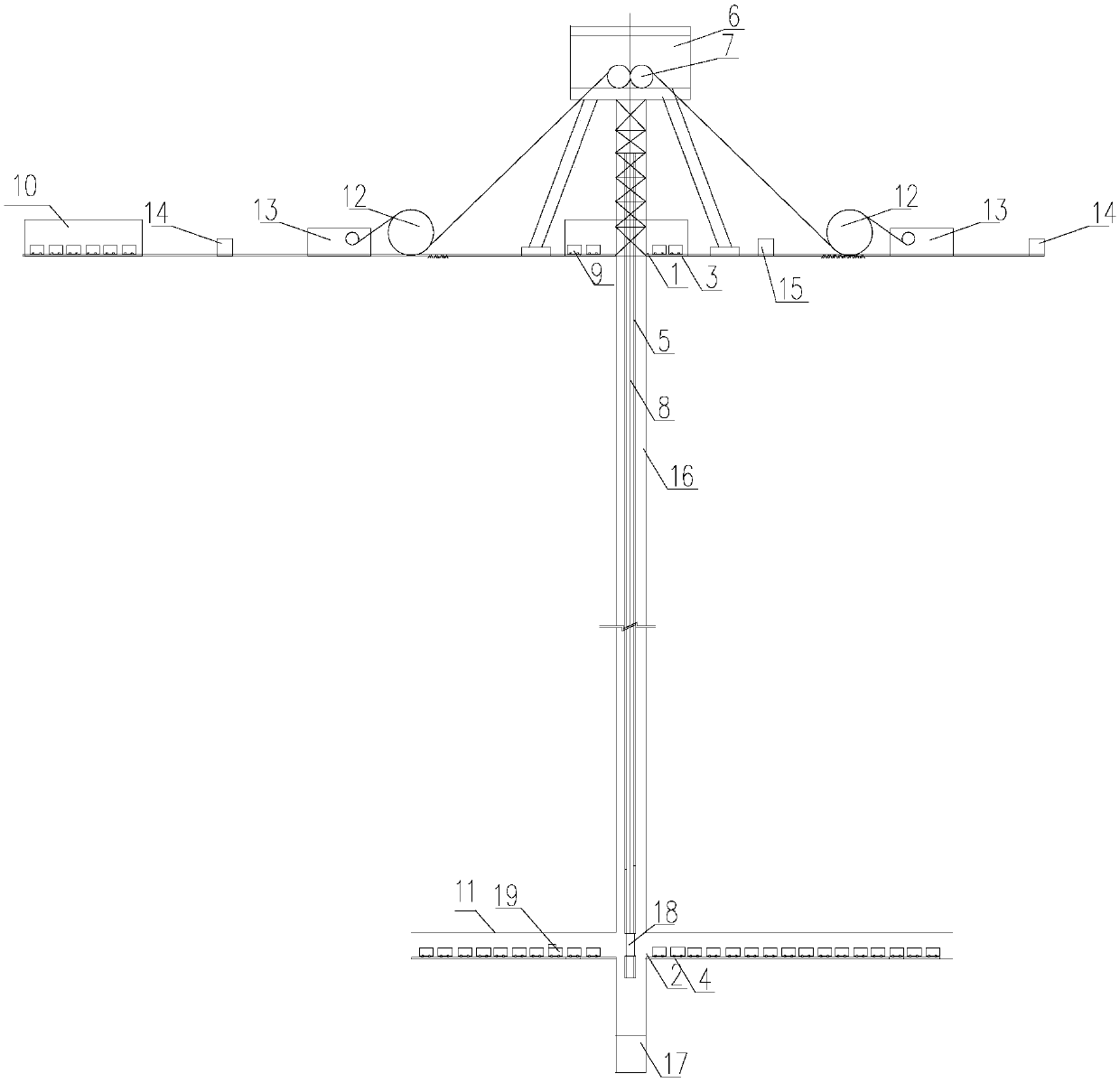
[0032] see figure 1 The gravitational energy storage system based on mine vertical shaft, lifting and transportation system provided by the present invention includes a wellhead platform 1, a bottom parking platform 2, a wellhead driving equipment 3, a bottom driving equipment 4, a shaft equipment tank road 5, Derrick 6, derrick top wheel 7, steel wire rope 8, equal-heavy mine car with counterweight (hereinafter referred to as mine car 9), machine repair garage workshop 10, bottom shaft yard and chamber 11, wire rope winch 12, electric generator integrated machine 13 and Control system 14, transformer 15, shaft 16, water 17, cage 18 and battery locomotive 19. The mine car 9 with the same counterweight is parked near the wellhead platform 1 and the well bottom parking platform 2. Utilize the wellbore equipment tank road 5 between them as the heavy object glide track, be provided with a set of electric generator integrated machine 13.

[0033] A wire rope winch 12 and an elect...


PUM


Abstract

The invention discloses a gravity energy storage system of a hoisting and transporting system based on a mine vertical shaft. The gravity energy storage system comprises derrick hoisting sheaves, steel wire rope winches, electric power generation integrated machines and control systems. A derrick is located over the shaft mouth of a vertical shaft. The derrick hoisting sheaves are arranged on thederrick. A cage runs on a vertical shaft device cage guide and can move up and down along the vertical shaft device cage guide. The cage is connected with one ends of steel wire ropes, and the other ends of the steel wire ropes are wound around the steel wire rope winches. The steel wire rope winches are connected with the electric power generation integrated machines through mechanical transmission mechanisms. The electric power generation integrated machines are connected with a power grid through a transformer. Shaft mouth car operation devices and shaft bottom car operation devices are used for transferring and transporting mine cars onto a cage. The control systems are used for controlling the working conditions of the shaft mouth car operation devices, the shaft bottom car operationdevices and the electric power generation integrated machines. The gravity energy storage system is particularly suitable for reutilization of an abandoned mine vertical shaft and a mine about to dropout of use.

Description

technical field [0001] The invention belongs to the technical field of energy storage, and in particular relates to a gravity energy storage system based on a mine shaft shaft, lifting and transportation system. Background technique [0002] Existing power energy storage technologies include pumped water storage, compressed air energy storage, battery energy storage, flywheel energy storage, electrolyzed water energy storage, superconducting magnetic energy and supercapacitors. Among them, the pumped water storage technology is the most typical. The pumped water storage method has a large energy storage capacity and a fast response speed, so it is widely used. However, the construction of pumped storage power stations requires special geographical conditions. The construction of two reservoirs and dams requires a long construction period and huge initial investment, and can only be built in places with water sources, and the energy conversion efficiency is average (about 70%...

Claims


Application Information

Patent Timeline
Patent Type & Authority Applications(China)
IPC IPC(8): B66B15/00B66B15/08B66B17/04B66B17/16B66B17/30B66B5/28F03G3/00
CPCF03G3/00B66B5/28B66B15/00B66B15/08B66B17/04B66B17/16B66B17/30
Inventor 宋立平董宝光王东军王帅朱磊吴玉意
Owner 中煤能源研究院有限责任公司
Learn More