Flow electroporation device

A technology of flow electroporation and temperature control device, which is applied in the field of electroporation, which can solve the problems of electrode electric field intensity distribution change, electroporation result change, time-consuming and other problems, achieve less cell damage, improve electroporation efficiency, and facilitate operation Effect

Active Publication Date: 2019-04-26
ETTA BIOTECH
View PDF13 Cites 1 Cited by
  • Summary
  • Abstract
  • Description
  • Claims
  • Application Information

AI Technical Summary

Problems solved by technology

First, due to the time-consuming static chamber electroporation of a large number of samples, the cells used for each static electroporation will vary during the experiment
Second, this method is used only because it is believed that the optimal conditions for static chamber electroporation are the same as for flow electroporation, but it is not known whether this is true
However, due to the influence of the electrode structure and the surface roughness of the electrode material, if the bubbles stay inside the electroporation chamber, the electric field intensity distribution in the electrode will change because the bubbles do not conduct electricity; at the same time, the bubbles occupy the chamber, which will change the solution flow rate and cause cells to flow Changes in the number and intensity of current pulse signals received by the electrode area, resulting in changes in the results of electroporation

Method used


Image

  • Flow electroporation device
  • Flow electroporation device
  • Flow electroporation device

Examples


Embodiment 1

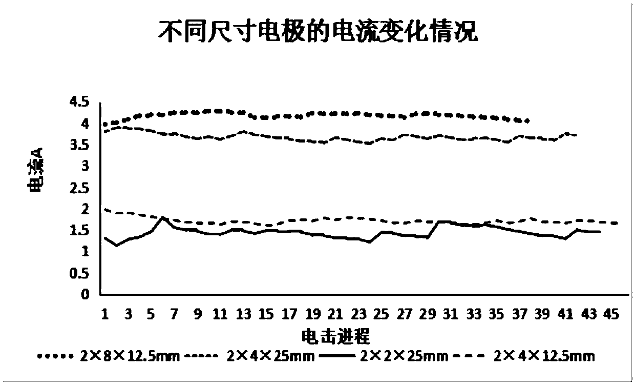
[0097] Electrode shape and size selection

[0098] The flow electroporation device of the present invention adopts planar electrodes, and the size of the planar electrodes determines the speed of processing cells per unit time, and the length, width and spacing of electroporation chambers have different effects. When the flow rate is constant, the length of the planar electrode affects the time of solution flow inside the electrode. Increasing the electrode length will increase the contact time of the bubbles with the electrode surface when they flow through the electrode area, increasing the probability of bubble retention. The width of the planar electrode affects the flow rate of the solution inside the electrode. The flow rate in the middle area of ​​the fluid is fast, and the flow rate in the edge area is slow. The larger the electrode width, the more obvious the deviation. The distance between planar electrodes affects the strength of the electric field. According to the...

Embodiment 2

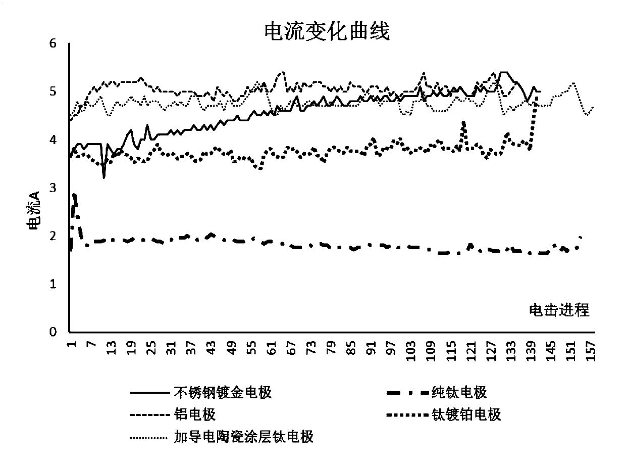
[0102] Choice of planar electrode material

[0103] In the flow electroporation device of the present invention, the research and development of the planar electrode material is the core content. The surface of the planar electrode should be smooth and flat, and the contact with the support should be smooth without step difference and form a sealed chamber to minimize the possibility of air bubble retention. Through the selection of electrode materials, optimization of electrode structure and control of electric field strength, the adverse effects of electrochemical reaction products on the electrotransfection effect during the electric shock process can be reduced.

[0104] Design of the experimental scheme: the types of planar electrode materials that can be selected in this embodiment are aluminum, 304 stainless steel, pure gold, gold-plated stainless steel, pure titanium, titanium with a conductive ceramic coating, pure platinum, platinum-plated titanium, and pure iridium; ...

Embodiment 3

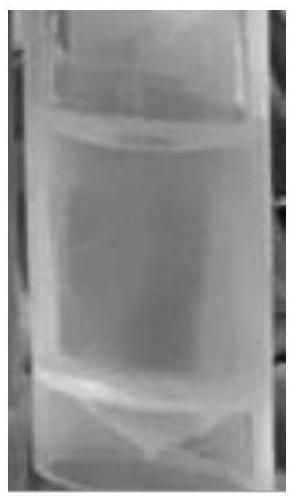
[0134] Selection of different ways for fluids to enter and exit the electroporation chamber

[0135] Experimental scheme design: The angle between the horizontal angle when the fluid enters the electroporation chamber and the horizontal angle when it flows in the electroporation chamber can be between 0° and 90°. When the angle is 0°, the fluid is positively entering and positively exiting. , when the angle is 90°, the fluid is side-in and side-out. The main way for the fluid to enter and exit is that the liquid inlet and outlet of the bracket extend in a straight line, so that the silicone tube at the proximal end of the electrode is connected in parallel to the electrode. The main way of side-in and side-out of the fluid is that the liquid inlet and outlet of the bracket form a 90° angle with the flat electrode, so that the silicone tube at the proximal end of the electrode is vertically connected to the electrode.

[0136] Choose titanium-platinum-plated planar electrode, ...


PUM

PropertyMeasurementUnit
thicknessaaaaaaaaaa
thicknessaaaaaaaaaa
diameteraaaaaaaaaa

Abstract

The invention relates to a flow electroporation device. The flow electroporation device comprises a support frame and planar electrodes used for limiting a fluid flowing channel, wherein two planar electrodes are embedded into the support frame in parallel; each planar electrode comprises a device which is electrically connected with a high-voltage pulse power supply, so that fluid moving along the fluid flowing channel passes through a pulsed electric field; materials of the planar electrodes are selected from one or several of aluminum, stainless steel, gold, silver, titanium, platinum, iridium, niobium, ruthenium, rhodium, molybdenum, tungsten and conductive ceramics or conductive materials taking gold, silver, titanium, platinum, iridium, niobium, ruthenium, rhodium, molybdenum, tungsten and conductive ceramics as coating layers or plating layers. According to the flow electroporation device, the shape of an inlet and an outlet in the support frame structure can be optimized, so that a cell-bioactive substance suspension solution can uniformly enter into an electroporation chamber; meanwhile, cells subjected to electric shock treatment and other materials generated by electrotransfection can also be smoothly discharged out of the electroporation chamber. The flow electroporation device can be applied to treatment of ultra-large volume of cell liquid; the electrotransfectionefficiency can be obviously improved; meanwhile, the survival rate of the cells can be obviously increased.

Description

technical field [0001] The invention relates to the field of electroporation, in particular to a flow electroporation device, a method and a device for delivering flowing bioactive substances into flowing living cells through an electric field. Background technique [0002] The phenomenon of electroporation was discovered in the 1970s. Cells are treated with an electric field to form micropores, but they do not cause permanent damage to the cells, and the micropores can reset by themselves. This discovery makes it possible for biologically active substances to enter cells. Existing studies have found that there are four phenomena that may play a role in the process of electroporation. The first phenomenon is insulation breakdown. Dielectric breakdown refers to the ability of high electric fields to create small micropores or holes in cell membranes. Once the micropores are created, cells can be loaded with bioactive substances. The second phenomenon is the insulating bun...

Claims


Application Information

Patent Timeline
Patent Type & Authority Applications(China)
IPC IPC(8): C12M1/42C12N15/87
CPCC12M23/16C12M35/02C12N15/87C12M41/12C12N13/00A61N1/327
Inventor 戴晓兵朱士英杨昌陈汪莹高腾森
Owner ETTA BIOTECH
Why Eureka
Try Eureka