All-optical diode controllable unidirectional optical transmission device and method
An all-optical diode and optical transmission technology, which is applied in the field of micro-nano photonics, can solve the problems such as controllable reversal of the conduction direction of signal light, and achieves the effect of simple structure and operation, and easy integration.
- Summary
- Abstract
- Description
- Claims
- Application Information
AI Technical Summary
Problems solved by technology
Method used
Image
Examples
Embodiment 1
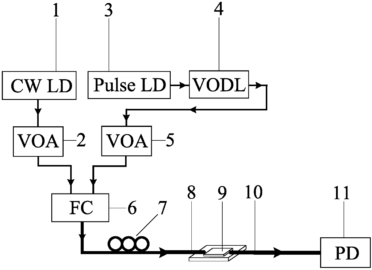
[0039] like figure 1 As shown, an all-optical diode controllable unidirectional optical transmission device in this embodiment includes a wavelength-tunable continuous wave laser (CW LD) 1, a first variable optical attenuator (VOA) 2, and a power-tunable ultrashort pulse Laser (Pulsed LD) 3, Variable Optical Delay Line (VODL) 4, Second Variable Optical Attenuator (VOA) 5, Fiber Coupler (FC) 6, Polarization Controller (PC) 7, Lens Fiber (LF ) 8. Asymmetric photonic crystal microcavity-waveguide structure 9, lens fiber (LF) 10, photodetector (PD) 11.
[0040] The wavelength tunable continuous wave laser 1 is used to provide signal light, its wavelength is continuously adjustable from 1529nm to 1609nm, the tuning accuracy is 1MHz, and the spectral line width is 100kHz; the ultrashort pulse laser 3 is used to provide pump light, and its center wavelength is λ= (1550±2)nm, the pulse width is 200fs, and the repetition frequency is 350MHz.
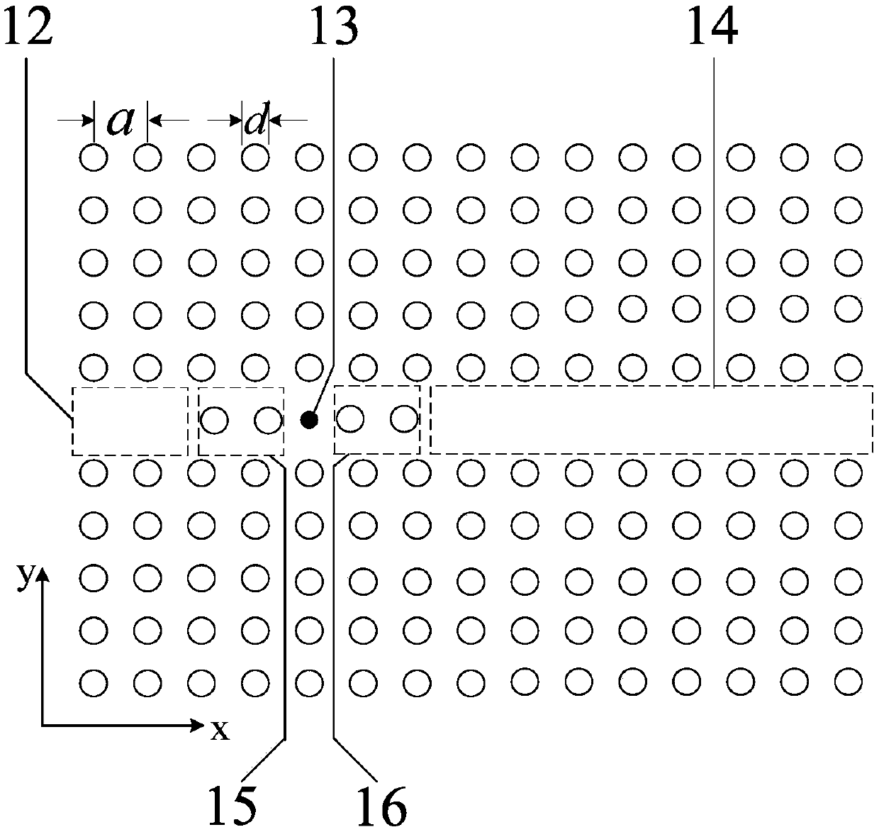
[0041] like figure 2 As shown, the pho...
Embodiment 2
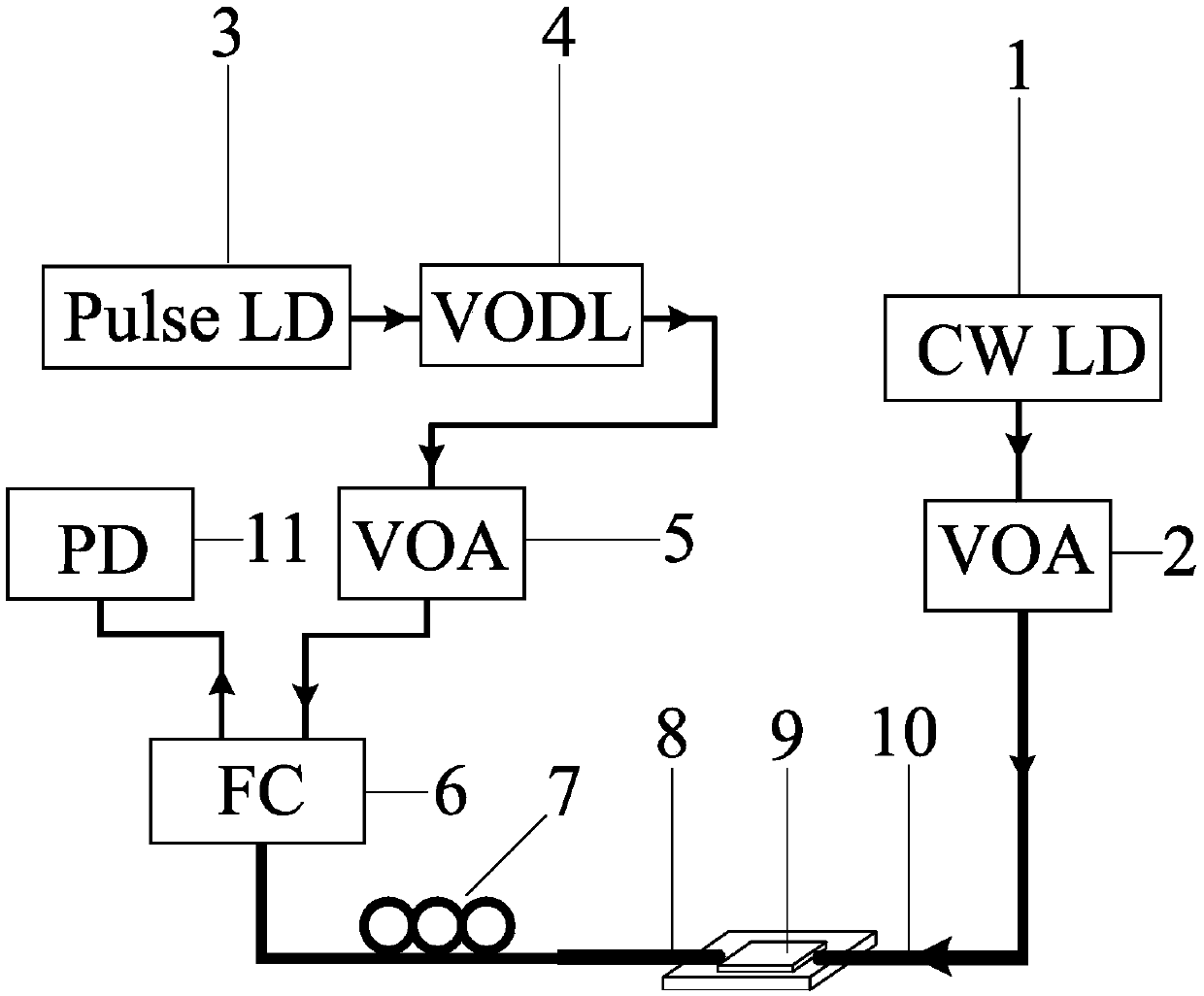
[0052] A kind of all-optical diode controllable unidirectional optical transmission device of this embodiment, in order to realize the controllable reversal of the conduction direction of the all-optical diode under the same signal light wavelength switch to reverse conduction), except for the following features, all the other features are the same as in Embodiment 1.
[0053] Delay the emission time t of the ultrashort pulse laser 3 relative to the continuous wave laser 1 d set as Figure 4 Arbitrary values shown in the middle triangle, these values represent the pulse delay time t required for the signal light to travel backward in order to reach the high transmission state of the microcavity bistability d value.
[0054] The signal light emitted by the continuous wave laser 1 is reversely incident from the photonic crystal waveguide 14 on the right side, and the adjustable optical delay line 4 is used to set the delayed emission time of the ultrashort pulse laser 3 co...
PUM
| Property | Measurement | Unit |
|---|---|---|
| Pulse width | aaaaa | aaaaa |
| Line width | aaaaa | aaaaa |
| Coefficient | aaaaa | aaaaa |
Abstract
Description
Claims
Application Information
 - R&D
- Intellectual Property
- Life Sciences
- Materials
- Tech Scout
- Unparalleled Data Quality
- Higher Quality Content
- 60% Fewer Hallucinations
Browse by: Latest US Patents, China's latest patents, Technical Efficacy Thesaurus, Application Domain, Technology Topic, Popular Technical Reports.
© 2025 PatSnap. All rights reserved.Legal|Privacy policy|Modern Slavery Act Transparency Statement|Sitemap|About US| Contact US: help@patsnap.com


