Filter dielectric resonator antenna with double-radiation zero value

A dielectric resonator and antenna technology, applied in resonant antennas, antennas, electrical short antennas, etc., can solve the problems of dielectric resonator antenna matching deterioration, difficult mode analysis, difficult filtering characteristics, etc., to achieve a simple structure, improve gain, gain flat effect

Inactive Publication Date: 2019-04-26
XIDIAN UNIV
View PDF8 Cites 14 Cited by
  • Summary
  • Abstract
  • Description
  • Claims
  • Application Information

AI Technical Summary

Problems solved by technology

Chinese patent authorization number CN109066072A discloses a broadband filter antenna. Although the invention has a 42% impedance bandwidth, its structure contains five layers of patches and four layers of dielectric materials, and the structure is relatively complicated.
[0007] The existing dielectric resonator antenna uses a dielectric material as the radiator of the

Method used


Image

  • Filter dielectric resonator antenna with double-radiation zero value
  • Filter dielectric resonator antenna with double-radiation zero value
  • Filter dielectric resonator antenna with double-radiation zero value

Examples


Embodiment Construction

[0031] The antenna of the present invention will be further described below in conjunction with the accompanying drawings and specific embodiments.

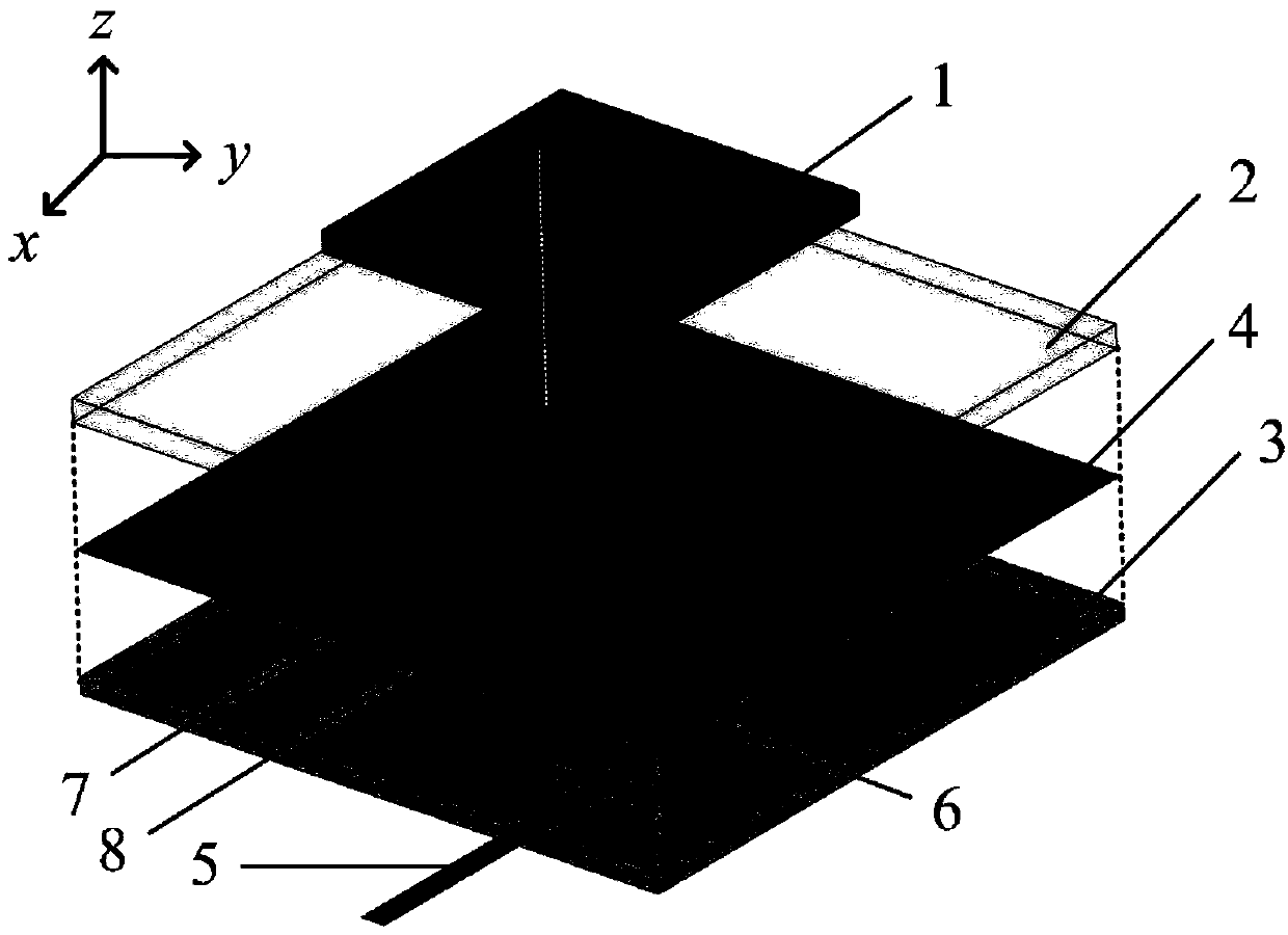
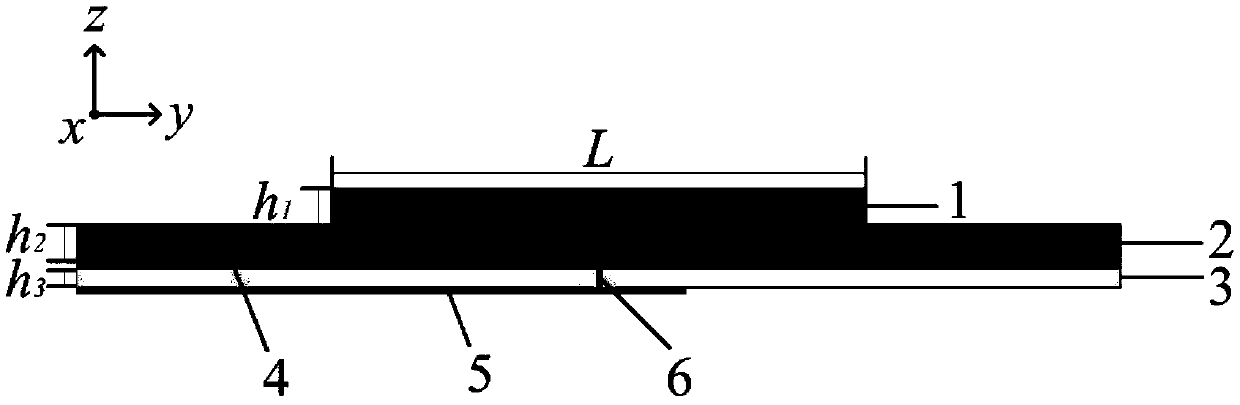
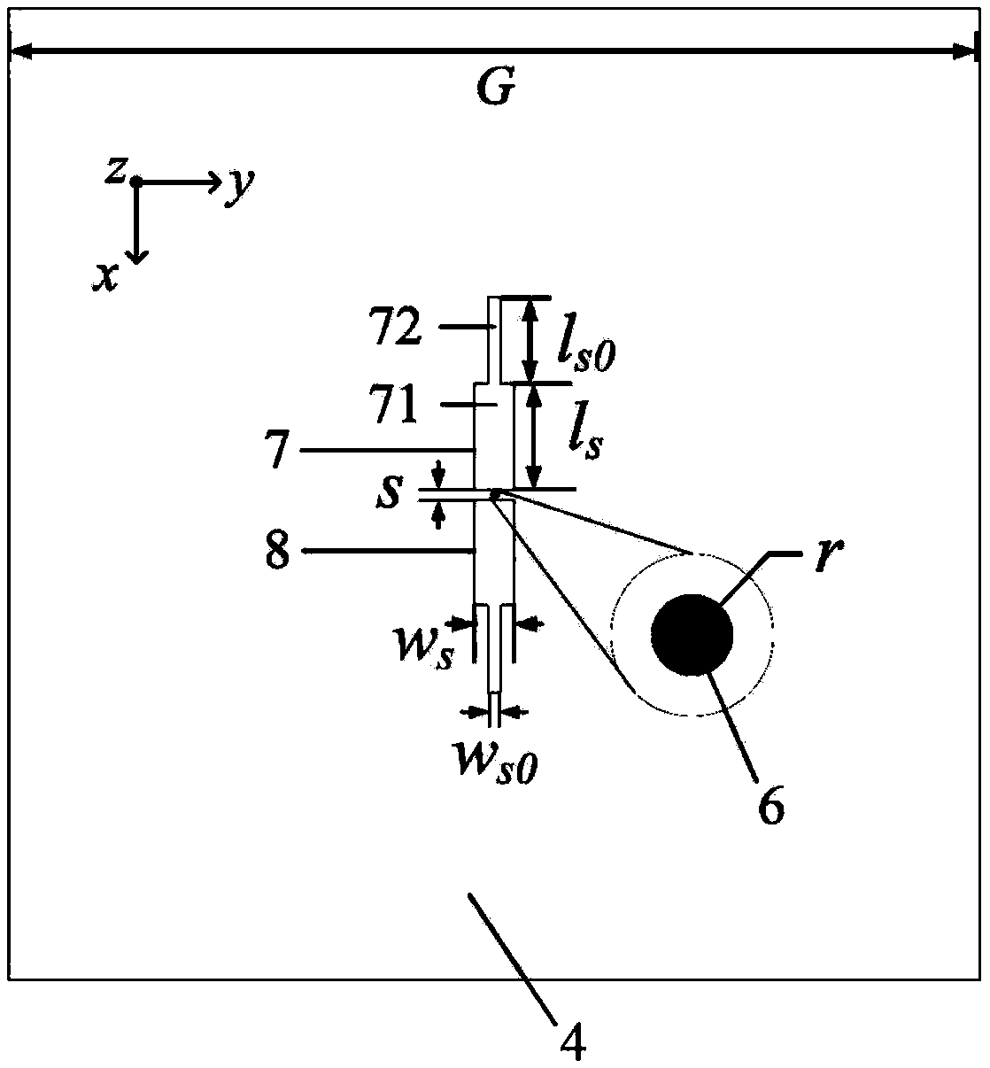
[0032] refer to figure 1 , the present invention includes a first dielectric block 1, a second dielectric plate 2, a dielectric substrate 3, a metal floor 4, a microstrip feeder 5, and two stepped gaps 7 and 8 printed on the surface of the metal floor 4. The metal floor 4 and the microstrip feeder 5 are printed on the upper and lower surfaces of the dielectric substrate 3 respectively; a short-circuit via hole 6 is provided at the geometric center of the dielectric substrate 3, and the metal floor 4 and the microstrip feeder 5 are connected through the short-circuit via 6 , constituting the feeding structure of the antenna; the three layers of dielectric materials, the first dielectric block 1, the second dielectric plate 2 and the dielectric substrate 3, are fixed and placed sequentially from top to bottom, with no spacing betwe...


PUM

PropertyMeasurementUnit
Widthaaaaaaaaaa
Widthaaaaaaaaaa
Heightaaaaaaaaaa

Abstract

The invention proposes a filter dielectric resonator antenna with a double-radiation zero value. The problems of surface wave loss and ohmic loss of an existing filter patch antenna are mainly solved.The filter dielectric resonator antenna comprises a dielectric substrate (3), a metal floor (4), a micro-strip feeder (5) and a short-circuit via hole (6). The metal floor and the micro-strip feederare printed on the upper surface and the lower surface of the dielectric substrate, and a feed structure is formed by connection through a short-circuit via hole: a second dielectric plate (2) and a first dielectric block (1) are fixed in sequence to the upper part of the metal floor, the first dielectric block acts as a radiator, and the second dielectric plate achieves good matching between theradiator and the feed structure; and two stepped slits (7) and (8) of the same size are engraved on the surface of the metal floor and used for slot coupling feeding to avoid the influence of parasitic radiation. The filter dielectric resonator antenna has good out-of-band rejection capability while maintaining high gain, the surface wave loss is avoided, the antenna radiation efficiency is improved, and the wireless signal can be received and transmitted in a C-band.

Description

technical field [0001] The invention belongs to the technical field of antennas, and in particular relates to a filter dielectric resonator antenna, which can be used for receiving and transmitting wireless signals in the C-band. Background technique [0002] With the rapid development of wireless communication, traditional single-function antennas can no longer meet the increasingly complex and diverse requirements of wireless communication systems. In order to adapt to the development of modern communication equipment, filter antennas have gradually gained people's attention. Since the concept of filter antenna was proposed, scholars at home and abroad have conducted extensive research on filter antenna. In the traditional filter antenna design, the antenna unit and the filter unit are designed separately, and then the two are cascaded, but this method is difficult to achieve a good match between the two. In order to solve this problem, it is necessary to add an addition...

Claims


Application Information

Patent Timeline
IPC IPC(8): H01Q1/36H01Q1/48H01Q1/50H01Q9/04
CPCH01Q1/36H01Q1/48H01Q1/50H01Q9/0457H01Q9/0485
Inventor 翁子彬高阳张立焦永昌
Owner XIDIAN UNIV
Why Eureka
Try Eureka