Millimeter wave array antenna module and mobile terminal

An array antenna and millimeter wave technology, which is applied in antennas, resonant antennas, antenna arrays, etc., can solve problems affecting the overall performance of millimeter wave phased array antennas, antenna gain attenuation, etc., and achieve the reduction of surface wave effects and antenna gain. Effect of attenuation suppression and improvement of antenna performance

Inactive Publication Date: 2019-04-26
AAC TECH NANJING
View PDF3 Cites 38 Cited by
  • Summary
  • Abstract
  • Description
  • Claims
  • Application Information

AI Technical Summary

Problems solved by technology

[0005] When the millimeter-wave phased array antenna scans to a large angle, it will be particularly affected by the surface wave, which will cause a large atte...

Method used


Image

  • Millimeter wave array antenna module and mobile terminal
  • Millimeter wave array antenna module and mobile terminal
  • Millimeter wave array antenna module and mobile terminal

Examples


Embodiment Construction

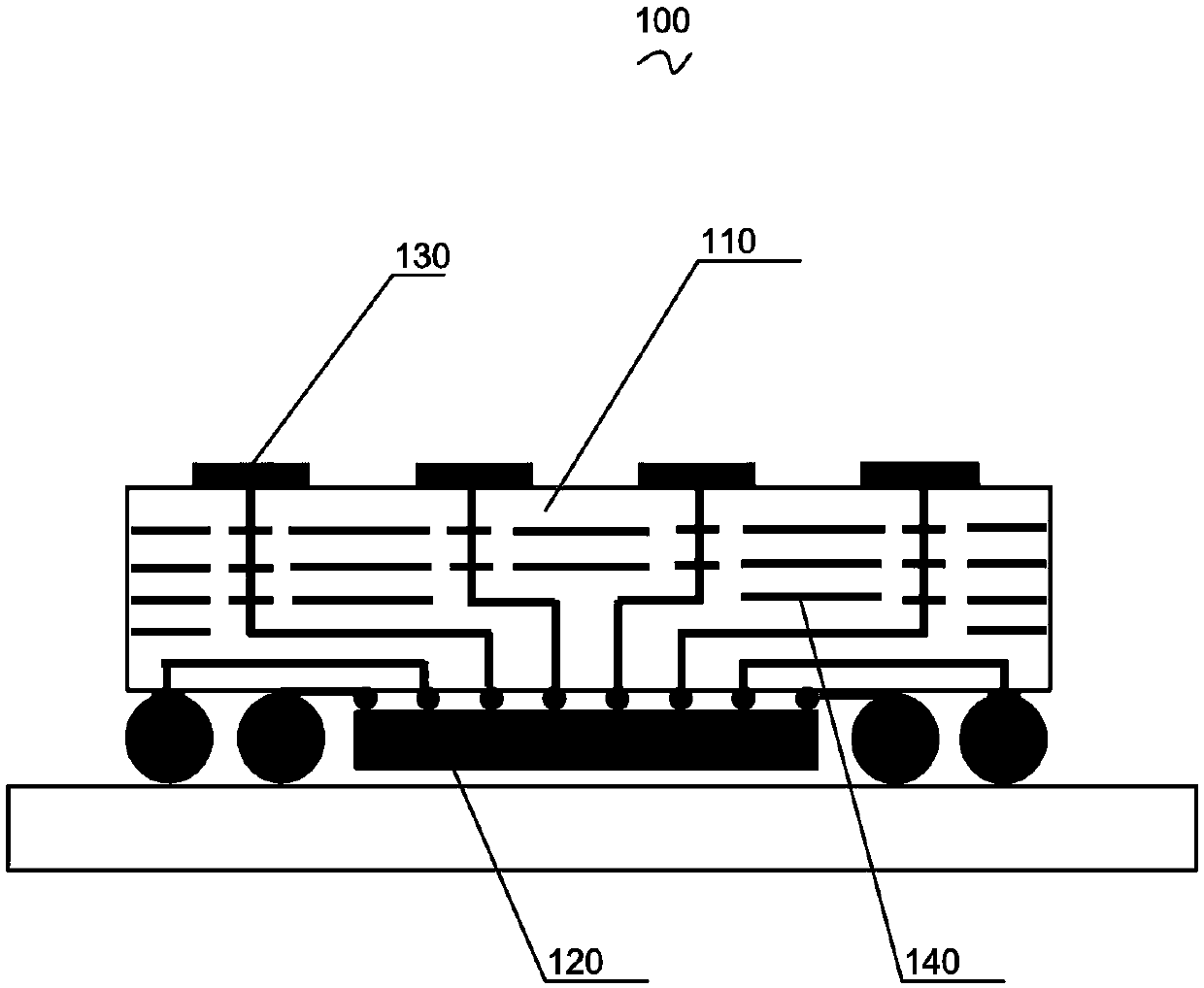
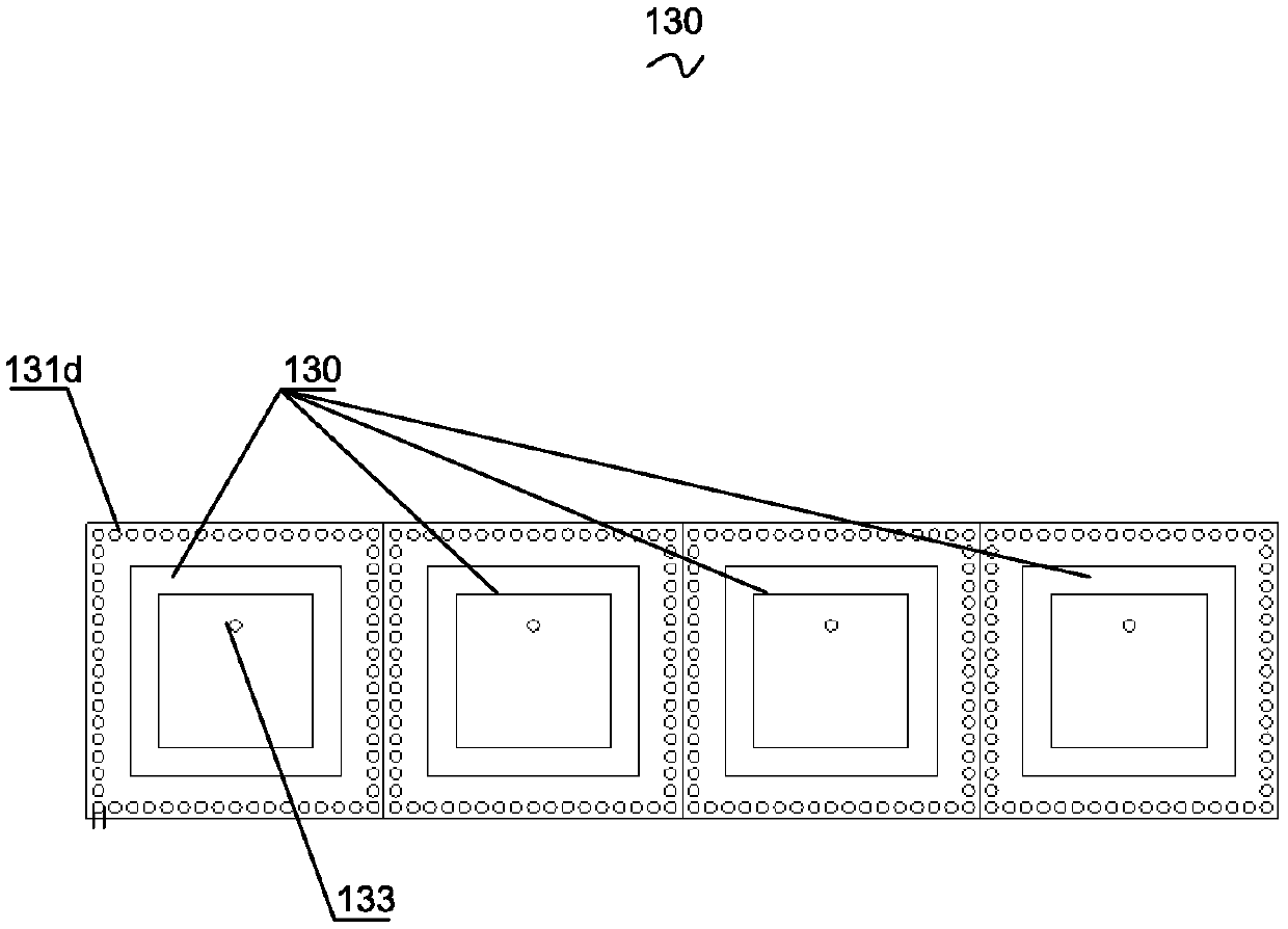
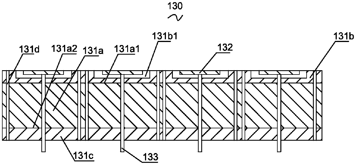
[0019] Combine below Figure 1 to Figure 3 The present invention is described in detail.

[0020] The first aspect of the present invention relates to a millimeter-wave array antenna module 100 for a mobile terminal. The mobile terminal may be, for example, a mobile phone, a computer, or a tablet. Such as figure 1 and figure 2 As shown, the millimeter wave array antenna module 100 includes a dielectric substrate 110, a radio frequency integrated circuit chip 120 attached to one side of the dielectric substrate 110, and a radio frequency integrated circuit chip 120 disposed on the side of the dielectric substrate 110 away from the radio frequency integrated circuit chip. A plurality of antenna units 130 arranged in an array and a feeding network 140 formed in the dielectric substrate 110 . Each of the antenna units 130 is electrically connected to the radio frequency integrated circuit chip 120 through the feed network 140, and each of the antenna units 130 includes a subst...


PUM


Abstract

A millimeter wave array antenna module and a mobile terminal are provided. The millimeter wave array antenna module includes a dielectric substrate, a radio frequency integrated circuit chip attachedto one side of the dielectric substrate, a plurality of antenna units arranged in an array on one side of the dielectric substrate away from the radio frequency integrated circuit chip and a feed network formed in the dielectric substrate. Each antenna unit is electrically connected to the radio frequency integrated circuit chip through the feed network, each antenna unit comprises a chip integration waveguide with a back cavity and a patch antenna attached to the back cavity. By means of structure of the chip integration waveguide and the patch antenna attached to the back cavity, the surfacewave effect can be reduced effectively, a phased array antenna can obtain larger scanning angle, and the antenna performance can be further improved during large angle scanning.

Description

【Technical field】 [0001] The invention relates to the technical field of antenna structures of mobile terminals, in particular to a millimeter wave array antenna module and a mobile terminal. 【Background technique】 [0002] As 5G is the research and development focus of the global industry, it has become an industry consensus to develop 5G technology and formulate 5G standards. At the 22nd meeting of ITU-RWP5D held in June 2015, the International Telecommunication Union ITU clarified three main application scenarios of 5G: enhanced mobile broadband, large-scale machine communication, and high-reliability and low-latency communication. These three application scenarios correspond to different key indicators. In the enhanced mobile bandwidth scenario, the user peak speed is 20Gbps, and the minimum user experience speed is 100Mbps. At present, 3GPP is standardizing 5G technology. The first 5G non-independent networking (NSA) international standard was officially completed and ...

Claims


Application Information

Patent Timeline
IPC IPC(8): H01Q21/08H01Q21/00H01Q1/38H01Q1/50H01Q1/22H01Q1/24
CPCH01Q1/2266H01Q1/2283H01Q1/243H01Q1/38H01Q1/50H01Q21/0006H01Q21/08H01Q3/38H01Q9/0407
Inventor 邾志民雍征东夏晓岳王超
Owner AAC TECH NANJING
Why Eureka
Try Eureka