
Internet-of-Things-based intelligent aeration pool for biological treatment of wastewater

A biological treatment and intelligent technology, applied in the direction of sustainable biological treatment, biological water/sewage treatment, water treatment parameter control, etc., can solve problems such as more cost, decreased rate of dissolved oxygen in wastewater, and decreased practicability of aeration tanks , to achieve the effect of speeding up the aeration efficiency and improving the aeration efficiency

Inactive Publication Date: 2019-04-30
NANJING LINGYA AUTOMOBILE TECH RES INST
View PDF0 Cites 1 Cited by
  • Summary
  • Abstract
  • Description
  • Claims
  • Application Information

AI Technical Summary

Problems solved by technology

However, during mechanical aeration, since the blades contact the entrapped air with the wastewater, and the oxygen content in the air is low, only 21%, the aeration tank needs to spend more time to integrate the wastewater into a certain amount of oxygen. As a result, the aeration efficiency of the aeration tank is lower. Not only that, in the existing aeration tank, due to the fixed position of the drive motor, it is necessary to discharge a certain amount of wastewater into the aeration tank, so that the impeller can stir the wastewater in the tank to complete the process. The aeration work, and the rotation track of the impeller is fixed, can only aerate the wastewater at a specific position in the tank, resulting in a decrease in the rate of dissolved oxygen in the wastewater, which leads to a decrease in the practicability of the existing aeration tank

Method used


Image

  • Internet-of-Things-based intelligent aeration pool for biological treatment of wastewater
  • Internet-of-Things-based intelligent aeration pool for biological treatment of wastewater
  • Internet-of-Things-based intelligent aeration pool for biological treatment of wastewater

Examples


Embodiment Construction

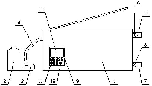
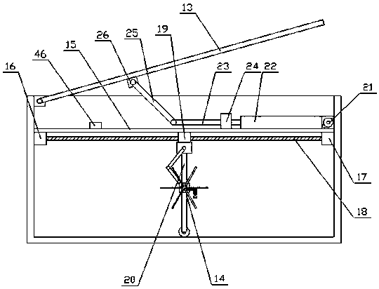
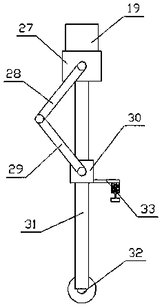
[0028] The present invention is described in further detail now in conjunction with accompanying drawing. These drawings are all simplified schematic diagrams, which only illustrate the basic structure of the present invention in a schematic manner, so they only show the configurations related to the present invention.

[0029] Such as Figure 1-Figure 5As shown, an intelligent aeration tank for wastewater biological treatment based on the Internet of Things includes a tank body 1, a controller 9, an exhaust pipe 5, a sewage pipe 7, an oxygen tank 2, a fan 3 and an air guide pipe 4, Described oxygen tank 2, fan 3 and air duct 4 are all arranged on one side of pool body 1, and described oxygen tank 2 communicates with fan 3, and described fan 3 communicates with pool body 1 through air duct 4, and described exhaust pipe 5 and the blowdown pipe 7 are all arranged on the other side of the pool body 1, the exhaust pipe 5 is located above the blowdown pipe 7, the exhaust pipe 5 is...


PUM


Abstract

The invention relates to an Internet-of-Things-based intelligent aeration pool for biological treatment of wastewater. The Internet-of-Things-based intelligent aeration pool comprises a pool boxy, anoxygen tank, a fan and a gas guide pipe, wherein a sealing plate, an aeration mechanism and two driving mechanisms are arranged in the pool body, the driving mechanism comprises a horizontal plate, asealing unit and a plane moving unit, the sealing unit comprises a gas pump, a gas cylinder, a piston and a support rod, and the plane moving unit comprises a translation unit and a lifting unit. According to the present invention, the sealing unit drives the sealing plate to rotate so as to make the pool body form a closed environment; the oxygen is input by the oxygen tank to increase the oxygenconcentration in the pool body, such that the more oxygen can be stirred during the rotating of the blade wheel so as to accelerate the aeration efficiency; and the moving of the aeration mechanism is achieved by the translation unit and the lifting unit realize, such that the equipment can perform aeration on various positions of wastewater, and the more oxygen is dissolved into the wastewater so as to improve the aeration efficiency and the practicability of the equipment.

Description

technical field [0001] The invention relates to the field of water treatment equipment, in particular to an intelligent aeration tank for wastewater biological treatment based on the Internet of Things. Background technique [0002] The aeration tank is a biochemical reactor designed according to the characteristics of microorganisms. As long as it uses the Martian sludge method for sewage treatment, a certain sewage residence time is provided in the tank to meet the oxygen required by aerobic microorganisms and the sufficient amount of sewage and activated sludge. Contact mixing conditions. The aeration tank is mainly composed of three parts: the tank body, the aeration system and the water inlet and outlet. The pool body is generally made of reinforced concrete, and its plane shape is rectangular, square and circular. [0003] At present, the methods used in the aeration tank mainly include blast aeration and mechanical aeration. The mechanical aeration generally uses th...

Claims


Application Information

Patent Timeline
IPC IPC(8): C02F3/02C02F3/20
CPCC02F3/02C02F3/205C02F2209/22C02F2209/42Y02W10/10
Inventor 易青芸
Owner NANJING LINGYA AUTOMOBILE TECH RES INST
Learn More