Check patentability & draft patents in minutes with Patsnap Eureka AI!

Current sharing circuit and current sharing system when inverters are connected in parallel at high frequency

An inverter and parallel technology, applied in the direction of converting AC power input to DC power output, electrical components, output power conversion devices, etc., can solve the problems of reduced system power density, inconsistent heating of inverters, and uneven output current. , to suppress the circulation phenomenon, improve power density and overall work efficiency, and reduce maintenance costs.

Active Publication Date: 2020-12-15
HUAWEI TECH CO LTD
View PDF3 Cites 0 Cited by
  • Summary
  • Abstract
  • Description
  • Claims
  • Application Information

AI Technical Summary

Problems solved by technology

[0008] When multiple modules are connected in parallel for power supply, the parallel connection between high-frequency modules may cause uneven output current of each parallel module due to parameter differences and drive delays of each parallel module, and some modules have large output currents. , and some output currents are small, which leads to inconsistent heat generation among inverters, and in severe cases, it may even cause an explosion.
[0009] The traditional technology is to reserve a larger design margin so that the module with the most serious heat generation can also meet the temperature rise requirements, but too large a redundant design will lead to a reduction in the power density and reliability of the system

Method used


Image

  • Current sharing circuit and current sharing system when inverters are connected in parallel at high frequency
  • Current sharing circuit and current sharing system when inverters are connected in parallel at high frequency
  • Current sharing circuit and current sharing system when inverters are connected in parallel at high frequency

Examples


Embodiment 1

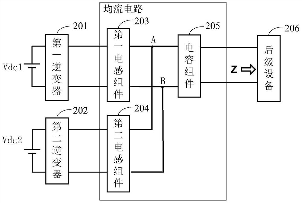
[0100] see figure 2 , is a circuit diagram of a current sharing circuit when inverters are connected in parallel at high frequency provided in this embodiment.

[0101] The current sharing circuit is applied to at least the following two inverters: the first inverter 201 and the second inverter 202 . The output terminal of the first inverter 201 and the output terminal of the second inverter 202 are connected in parallel at a common parallel point.

[0102] The method provided in the embodiment of the present application is suitable for high-frequency parallel connection of inverters. High-frequency parallel connection means that the midpoint voltage of the high-frequency output bridge arm of the inverter is connected in parallel, and the frequency is generally hundreds of Hz to hundreds of kHz. The high frequency output voltage of the inverter is different from the power frequency output voltage of the inverter. The high frequency output voltage of the inverter is usually ...

Embodiment 2

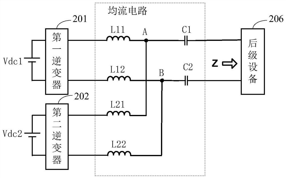
[0161] see image 3 , which is a circuit diagram of another current sharing circuit when inverters are connected in parallel at high frequency provided in this embodiment.

[0162] Such as image 3 As shown, the common parallel points include positive common parallel point A and negative common parallel point B.

[0163] The first inductance component includes: a first inductance L11 and a second inductance L12.

[0164] The first inductor L11 is connected between the positive output terminal of the first inverter and the positive common parallel point A; the second inductor L12 is connected between the negative output terminal of the first inverter and the negative common parallel point B.

[0165] The second inductance component includes: a third inductance L21 and a fourth inductance L22.

[0166] The third inductor L21 is connected between the positive output terminal of the second inverter and the positive common parallel point A; the fourth inductor L22 is connected b...

Embodiment 3

[0181] see Figure 5 , which is a circuit diagram of another current sharing circuit when inverters are connected in parallel at high frequency provided in this embodiment.

[0182] Wherein, the common parallel points include positive common parallel point A and negative common parallel point B.

[0183] The first inductance component includes: a first inductance L1.

[0184] The first inductor L1 is connected between the positive output terminal of the first inverter and the positive common parallel point A.

[0185] The second inductance component includes: a third inductance L3.

[0186] The third inductor L3 is connected between the positive output terminal of the second inverter and the positive common parallel point A.

[0187] The capacitor component includes: a first capacitor C1.

[0188] The first capacitor C1 is connected between the positive common parallel point A and the equipment connected to the rear stage of the inverter.

[0189]Compared with the current...


PUM


Abstract

The present application discloses a current sharing circuit and a current sharing system when inverters are connected in parallel at high frequency, which are used to realize current sharing between inverters, and can be applied to wireless charging scenarios in the field of electric vehicles. Applied to at least the following two inverters: the first inverter and the second inverter; the output terminals of the first inverter and the output terminals of the second inverter are connected in parallel at a common parallel point; the current sharing circuit includes: The first inductance component, the second inductance component and the capacitor component; the first inductance component is connected between the output end of the first inverter and the common parallel point, and the second inductance component is connected between the output end of the second inverter and the common Between the parallel points; the capacitor component is connected between the common parallel point and the subsequent equipment connected to the current sharing circuit; the first inductance component and the second inductance component are connected in parallel to form an equivalent inductance; the capacitor component and the equivalent inductance form a series resonance , and the frequency of the series resonance is the same as the switching frequency of the inverter. The circuit ensures current sharing when the inverters are connected in parallel, and the heat distribution of each inverter is even, which improves the power density and work efficiency.

Description

technical field [0001] This application relates to the technical field of power electronics, in particular to a current sharing circuit and a current sharing system when inverters are connected in parallel at high frequency. Background technique [0002] With the depletion of energy and the increasingly serious environmental pollution, the application of new energy vehicles is becoming more and more popular, such as electric vehicles. However, the charging problem of electric vehicles has become an urgent problem to be solved. At present, the development of wired charging piles is very fast, but one problem faced by charging is that the charging time of low power is relatively long. If electric vehicles can be charged as fast as gasoline vehicles, it must Increase charging power. Therefore, wired charging has been developed in the direction of 350kW and 500kW. [0003] However, the problem faced by wired charging is that wired charging requires the operator to manually plu...

Claims


Application Information

Patent Timeline
Patent Type & Authority Patents(China)
IPC IPC(8): H02M7/493H02M1/12
CPCH02M1/126H02M7/493H02M1/123
Inventor 毛云鹤武志贤刘彦丁
Owner HUAWEI TECH CO LTD
Features
  • R&D
  • Intellectual Property
  • Life Sciences
  • Materials
  • Tech Scout
  • Unparalleled Data Quality
  • Higher Quality Content
  • 60% Fewer Hallucinations
Learn More