
Orbital angular momentum generating device and method of polarization modulation orbital angular momentum

An orbital angular momentum generating device technology, which is applied in the field of orbital angular momentum generating devices of polarization modulated orbital angular momentum, can solve the problems of large size of the device, unfavorable integration, single mode, inability to meet the application of quantum coding and quantum key distribution, etc. Achieve the effect of compact overall structure and low production cost

Active Publication Date: 2019-05-03
GUANGDONG INCUBATOR TECH DEV CO LTD
View PDF8 Cites 6 Cited by
  • Summary
  • Abstract
  • Description
  • Claims
  • Application Information

AI Technical Summary

Problems solved by technology

However, these devices have their own limitations. For example, the spiral phase plate can only realize OAM of a single mode; although the spatial light modulator can realize dynamic modulation of different OAM modes, its response rate is generally below KHz, which greatly limits Its application value is limited, and the large size of the device is not conducive to integration; the q-plate can realize the conversion between spin-orbit angular momentum and generate the corresponding OAM superposition state, but it is difficult to generate high-dimensional OAM, and the generated OAM mode is relatively single
[0004] At the same time, in the prior art, such as Alipasha Vaziri et al. have realized the preparation of the OAM superposition state by computer-generated holograms and interferometry, but the resulting mode is single and cannot be dynamically modulated (Alipasha Vaziri, atal.Superpositions of the orbital angular momentum for applications inquantum experiments.Journal of Optics B: Quantum and Semiclassical Optics, 2002, 4(2), 1-19.); Cai Xinlun's group at Sun Yat-sen University integrates superimposed Angular gratings can be used to generate arbitrary OAM superposition states, but the OAM superposition states generated by it are directly related to the wavelength of the incident light, which limits its application in the field of communication (Xiao, Q, atal. Generation of photonic orbital angular momentum superposition states using vortex beam emitters with superimposed gratings. Optics Express, 2016, 24(4), 3168.); For example, the patent CN101251655A uses a diffraction grating and a Duff prism to realize the superposition of the OAM state, which can produce a reverse superposition state of multiple different modes of orbital angular momentum , but can only statically generate a superposition state, and cannot be dynamically modulated; the patent CN101726868A can dynamically generate an OAM superposition state, but the generation rate is limited by the spatial modulator, and it is difficult to integrate; although the patent CN104065418A has realized an integrated orbital angular momentum mode transmitter, but still unable to dynamically adjust
Prior art, Chinese patent publication CN104007567A provides a vortex beam generation system method with tunable orbital angular momentum state. This method uses a spiral phase plate to realize the dynamic modulation of OAM, which improves the generation rate of OAM, but can only generate A single OAM state cannot produce a superposition state;
[0005] To sum up, the current existing technology still cannot meet the application of quantum coding and quantum key distribution (QKD) in the future.

Method used


Image

  • Orbital angular momentum generating device and method of polarization modulation orbital angular momentum
  • Orbital angular momentum generating device and method of polarization modulation orbital angular momentum
  • Orbital angular momentum generating device and method of polarization modulation orbital angular momentum

Examples


Embodiment Construction

[0045] The specific embodiments of the present invention will be further described below in conjunction with the accompanying drawings.

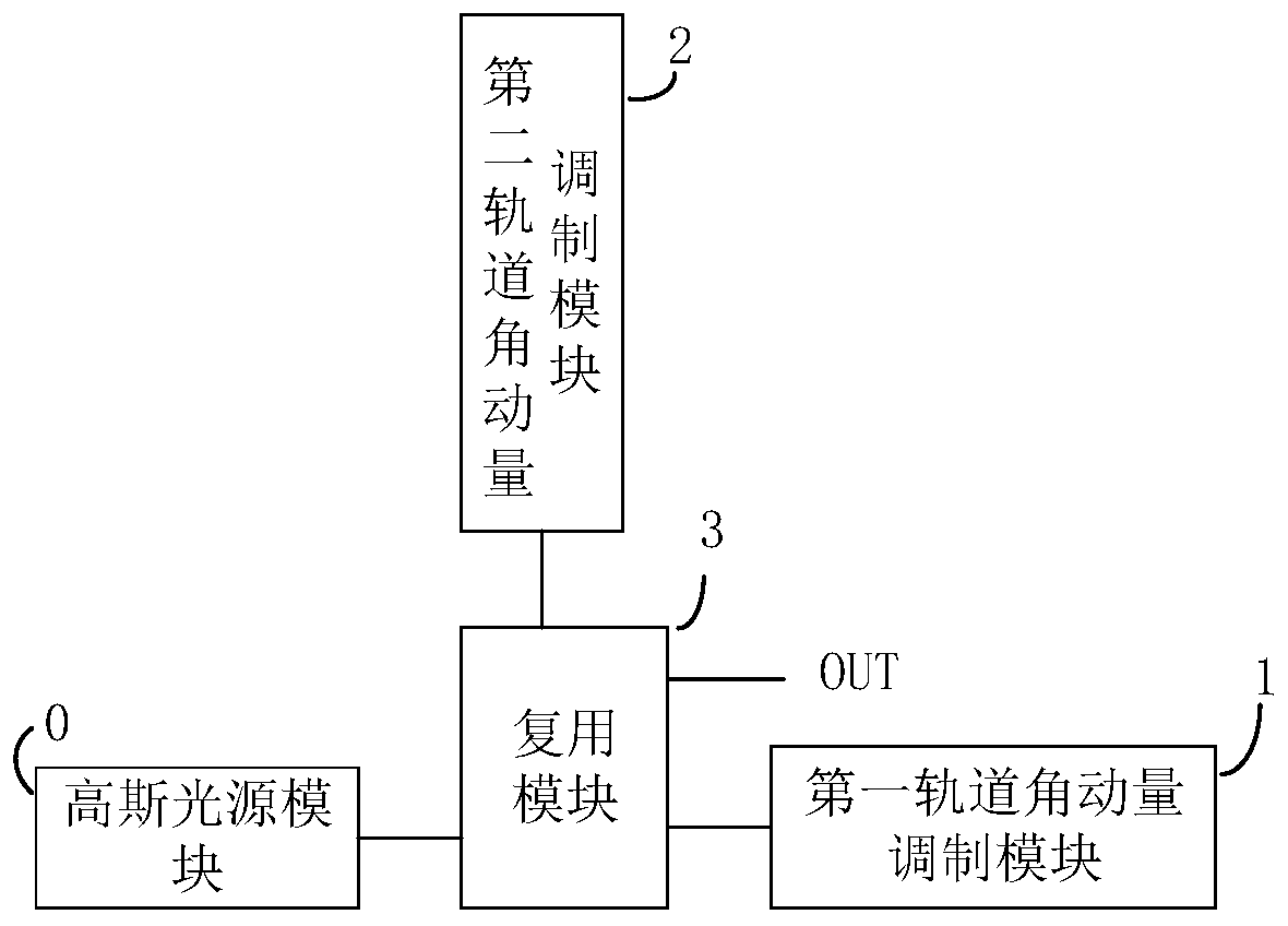
[0046] Such as figure 1 As shown, a polarization-modulated orbital angular momentum generation device provided by the present invention includes a Gaussian light source module 0 , a first orbital angular momentum modulation module 1 , a second orbital angular momentum modulation module 2 and a multiplexing module 3 .

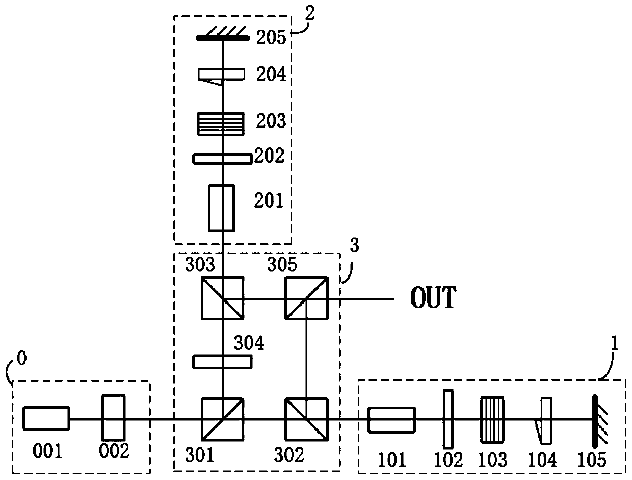
[0047] Such as figure 2 As shown, the Gaussian light source module 0 includes: a pumping light source 001 and a polarizer 002; the pumping light source 001 generates Gaussian pulsed light;

[0048] The polarizer 002 modulates the Gaussian pulse beam into the required polarization state;

[0049] The first orbital angular momentum modulation module 1 includes: a first delayer 101, a first quarter-wave plate 102, a first holographic grating switch 103, a first spiral phase plate 104 and a first total reflection mirror 105;

...


PUM


Abstract

The invention provides the orbital angular momentum generating device and method of a polarization modulation orbital angular momentum. The device comprises a Gaussian light source module, a first orbital angular momentum modulation module, a second orbital angular momentum modulation module and a reuse module. When the device works, the Gaussian light source module generates the Gaussian light beam of any polarization states and the light beam enters into the reuse module; the reuse module decomposes the Gaussian light beam into two polarization components whose polarization directions are horizontal and vertical, and the components are introduced into the first or second orbital angular momentum modulation module; the modulation module carries out polarization-independent orbital angularmomentum modulation on the two components, and the two modulated optical components are returned to the reuse module; and the reuse module superposes the two optical components, and finally outputs an orbital angular momentum state or superposition state. The structure is compact, manufacturing cost is low, a required device and technology are mature, the orbital angular momentum state and the superposition state of any topological charge number can be generated at a high speed, and a rate can reach the order of MHz.

Description

technical field [0001] The invention relates to the technical field of quantum information and optical communication, in particular to an orbital angular momentum generation device and method for polarization modulation orbital angular momentum. Background technique [0002] Quantum cryptography is an information technology with provable security at present, and high bit rate long-distance transmission is an urgent problem to be solved by quantum cryptography. Scientists have found that using multiple degrees of freedom and uncertainty relations to multiplex and modulate signals can expand the transmission capacity and increase the key rate. Among them, orbital angular momentum (OAM) is another important degree of freedom for quantum cryptography modulation besides polarization, phase and wavelength. A beam with orbital angular momentum (OAM, Orbital Angular Momentum) has a phase factor exp(ilθ), carrying an orbital angular momentum of lh, where θ is the azimuth angle, and ...

Claims


Application Information

Patent Timeline
Patent Type & Authority Applications(China)
IPC IPC(8): G02B27/28G02B27/42G02B5/30G02F1/03
CPCG02F1/03G02B27/283G02B27/286H04B10/11H04J14/06G02B27/4233G02B5/3083G02B27/0944H04B10/532H04B10/70G02B5/32
Inventor 郭邦红何翼龙
Owner GUANGDONG INCUBATOR TECH DEV CO LTD
Learn More