[0018] The following will clearly and completely describe the technical solutions in the embodiments of the present invention with reference to the accompanying drawings in the embodiments of the present invention. Obviously, the described embodiments are only some, not all, embodiments of the present invention. Based on the embodiments of the present invention, all other embodiments obtained by persons of ordinary skill in the art without making creative efforts belong to the protection scope of the present invention.
[0019] The purpose of the present invention is to provide an imaging device for non-destructive detection of dental hard tissue diseases, which can reduce radiation damage, improve imaging clarity, and improve the prevention and treatment effects of dental diseases.
[0020] In order to make the above objects, features and advantages of the present invention more comprehensible, the present invention will be further described in detail below in conjunction with the accompanying drawings and specific embodiments.
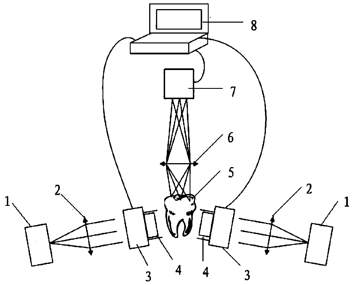
[0021] figure 1 It is a composition diagram of an imaging device for non-destructive detection of dental hard tissue diseases according to an embodiment of the present invention. An imaging device for non-destructive detection of dental hard tissue diseases, comprising: a near-infrared light source system, an optical image detection system, and a computer; the number of the near-infrared light source systems is two, and each of the near-infrared light source systems is symmetrically distributed in the waiting area. Measuring both sides of the tooth 5, the near-infrared light source system includes a near-infrared light source 1, a collimation adjustment mirror 2, a liquid crystal optical modulator 3 and an optical fiber collimator 4; the near-infrared light source 1, the collimation adjustment mirror 2. The liquid crystal optical modulator 3 and the fiber collimator 4 are arranged sequentially; the liquid crystal optical modulator 3 is connected to the computer 8, and the computer 8 is connected to the optical image detection system;
[0022] The light emitted by the near-infrared light source 1 is collimated by the collimating mirror 2 and then projected to the liquid crystal optical modulator 3, and the computer 8 performs an operation on the liquid crystal optical modulator according to the image information obtained by the optical image detection system. The light intensity of the modulator 3 is adjusted, and the adjusted light is projected onto both sides of the tooth to be tested 5 through the optical fiber collimator 4; the optical image detection system acquires the lesion information on both sides of the tooth to be tested and The lesion information is uploaded to the computer 8, and the computer 8 displays the lesion information.
[0023] The optical image detection system includes an optical image detector 7 and an optical image detector lens 6, the optical image detector lens 6 is located directly above the tooth 5 to be tested, and the optical image detector 7 is located on the optical image Directly above the detector lens 6, the computer 8 is connected to the optical image detector 7.
[0024] The near-infrared light source 1 adopts a near-infrared laser or a diode near-infrared light source with a wavelength between 780nm and 1350nm.
[0025] The fiber collimator 4 is a bundle of capillary arrays formed by tens of thousands of hollow glass fibers that are hexagonally packed most tightly in cross-section, collimating light and transmitting it in parallel.
[0026] The liquid crystal optical modulator 3 is a transmissive liquid crystal optical modulator. The surface of the liquid crystal optical modulator 3 contains a micro-channel switch, and the computer 8 adjusts the light intensity by opening or closing the micro-channel switch. When the microchannel on the surface of the liquid crystal optical modulator 3 is in the "on" state, the near-infrared light flux of this channel enters the corresponding channel of the fiber collimator 4, is transmitted through the fiber collimator 4, and the modulated near-infrared light is projected to the One side of the tooth, the same optical path on the other side projects the near-infrared light to the other side of the tooth 5 to be tested, and the tooth irradiated by the two light sources is imaged on the optical image detector 7; on the contrary, when the surface of the liquid crystal optical modulator 3 When the micro-channel is in the "off" state, the near-infrared luminous flux of the channel weakens or disappears. The liquid crystal optical modulator 3 is a kind of unit containing many independent units, which are arranged in a two-dimensional array in space, and each unit can independently receive the control of optical signals or electrical signals, and modulate the intensity and phase of the light field through liquid crystal molecules. Equal parameters, transmissive liquid crystal optical modulator does not need absorbing device for reflected light, and the specific design is small in size and flexible in design.
[0027] The optical image detector 7 is a near-infrared CCD camera or a near-infrared CMOS camera or an InGaAs near-infrared camera.
[0028] The computer 8 is used to control the collection of image information associated with the teeth on the optical image detector, and to adjust the switching state and switching time of the microchannel corresponding to the corresponding position on the surface of the liquid crystal optical modulator according to the image obtained by the optical image detector, To achieve the purpose of adjusting the light intensity projected onto the local area of the tooth surface, thereby showing different levels of light intensity control for the corresponding image sensor pixels, and improving the dynamic range and contrast of tooth-related imaging.
[0029] The high dynamic range near-infrared imaging using the non-destructive detection of dental hard tissue lesions uses the light intensity modulation method of the liquid crystal optical modulator to irradiate the tooth to be tested with two near-infrared lights at the same time, generating a modulated light flux associated with the inside of the tooth. A near-infrared optical image detector acquires tooth images.
[0030] In actual use, first clean and wipe the optical lens assembly, follow figure 1 Optical path adjustment. Generally, the light emitted by a near-infrared laser or a near-infrared light source such as a diode with a wavelength between 780nm and 1350nm is adjusted into parallel light by the collimating mirror 2, and projected onto the surface of the liquid crystal optical modulator 3, according to the optical image detector 7 The contrast and saturation of the image are obtained, and the microchannel switch on the surface of the transmissive liquid crystal optical modulator 3 is controlled by the computer system 8 to adjust the change of light intensity. The modulated light flux is projected to the tooth to be tested through the optical fiber collimator 4 On both sides of 5, the light beams carrying tooth lesion information pass through the optical image detector lens 6 and converge to the optical image detector 7. The optical image detector 7 outputs digital image signals to the computer 8, which displays the tooth information.
[0031] An imaging device for non-destructive detection of dental hard tissue lesions of the present invention can replace the X-ray dental film machine on the market, can not limit the number of irradiations, shorten the patient's medical treatment cycle, and avoid the irradiation of the patient's and doctor's face and other parts Harm, compared with the general digital micromirror DMD, the transmissive liquid crystal optical modulator omits the reflection and absorption device and reduces the volume of the device.
[0032] Considering that there are many implementations based on the principle of the present invention, the implementations described here are only preferred solutions, and should not be regarded as limitations on the technical scope.
[0033] Each embodiment in this specification is described in a progressive manner, each embodiment focuses on the difference from other embodiments, and the same and similar parts of each embodiment can be referred to each other.
[0034]In this paper, specific examples are used to illustrate the principle and implementation of the present invention. The description of the above embodiments is only used to help understand the device of the present invention and its core idea; meanwhile, for those of ordinary skill in the art, according to the present invention Thoughts, there will be changes in specific implementation methods and application ranges. In summary, the contents of this specification should not be construed as limiting the present invention.