
A detector for repetitive positioning accuracy of moving parts

A technology of repeated positioning accuracy and moving parts, which is used in measuring/indicating equipment, metal processing mechanical parts, metal processing equipment, etc. Delivering effects with high precision and wide practicability

Active Publication Date: 2020-08-18
HENAN POLYTECHNIC UNIV
View PDF7 Cites 0 Cited by
  • Summary
  • Abstract
  • Description
  • Claims
  • Application Information

AI Technical Summary

Problems solved by technology

The number of drive shafts of the existing machine tool moving parts and the motion state mainly include: single-axis motion (linear motion, rotation and compound motion) and multi-axis space linkage compound motion. Regardless of the motion state, due to the limitations of space and position, calibration It is difficult to test the repeated positioning accuracy of the kinematic mechanism of the tool drive shaft during the motion state
[0003] Chinese Patent Publication No. CN108177024A discloses a tool post positioning accuracy and repeat positioning accuracy detection device and its use method, which is mainly based on the angle of the tool post user and the tool post reliability test, using laser interference technology to test different types of CNC horizontal The general-purpose, fast and convenient positioning accuracy and repeat positioning accuracy detection device of the servo tool holder does not disassemble the cutter head. The overall structure is complex, the accuracy requirements are relatively high, and the cost is high, which cannot fully meet the needs.

Method used


Image

  • A detector for repetitive positioning accuracy of moving parts
  • A detector for repetitive positioning accuracy of moving parts
  • A detector for repetitive positioning accuracy of moving parts

Examples


Embodiment approach 1

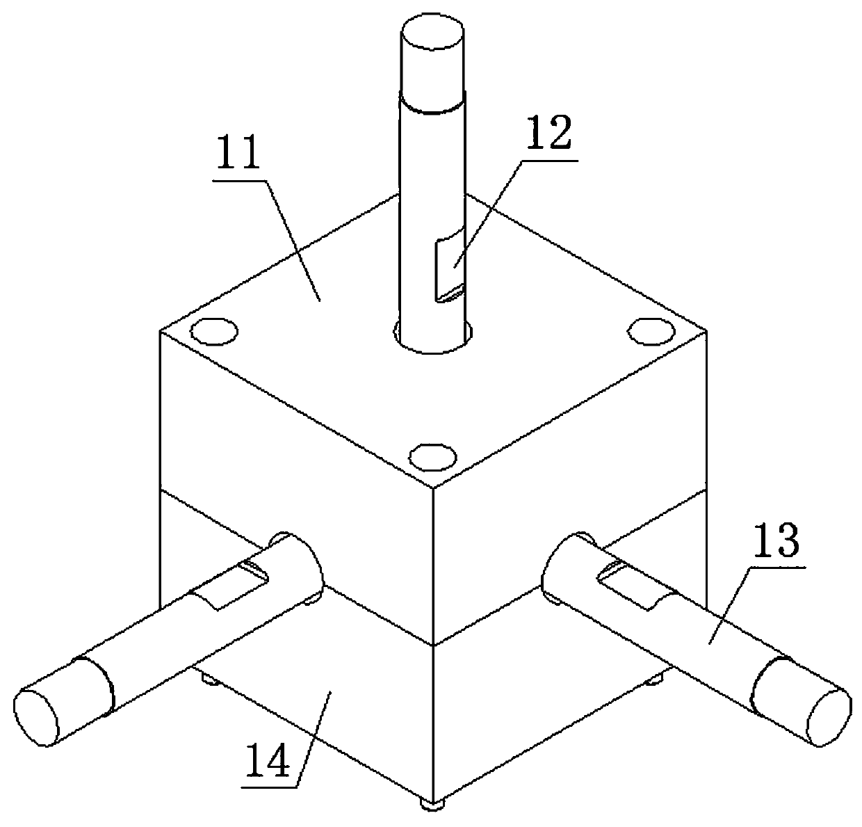
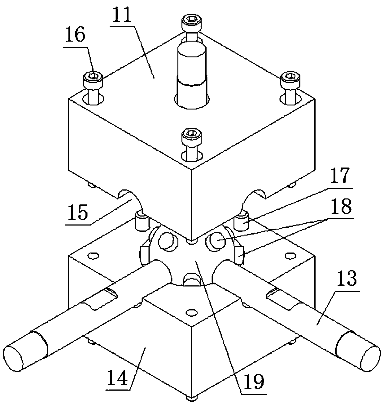
[0029] When it is implemented on a machining center mainly for turning, install the support plate 2 on the worktable of the machining center to ensure that the horizontal movement direction of the bottom three-dimensional sliding table 3 is the same as the two horizontal movement directions of the moving parts of the machining center, and the detector 1 The vertical position makes the protruding end of the detection arm 13 rigidly fixed with the moving parts of the machining center, and can also be fixed by adding necessary tooling. Set the moving speed and stroke of the moving parts of the machining center, and at the same time control the sliding of the three-dimensional sliding table 3 in the horizontal moving direction, so that the moving speed and stroke of the detector 1 are consistent with the moving parts of the machining center. During the process, the spatial jump of the components will be transmitted to the sensor ball 19 through the detection arm 13 in real time and...

Embodiment approach 2

[0031] When implemented on a machining center mainly based on milling, install the support plate 2 on the worktable of the machining center, adjust the movement of the three-dimensional sliding table 3 in all directions so that the extended end of the detection arm 13 can be rigidly fixed to the moving parts of the machining center It can also be fixed by adding necessary tooling. Since the moving parts of the machining center of the milling machine are in the form of rotation and movement, when performing repeated positioning accuracy detection on the moving parts of the machining center mainly based on milling, it is necessary to convert the runout during the rotation of the moving parts of the machining center into a fixed-point runout. At the same time, set the moving speed and stroke of the moving parts of the machining center, and at the same time control the sliding of the three-dimensional sliding table 3 in the horizontal moving direction, so that the moving speed and ...

Embodiment approach 3

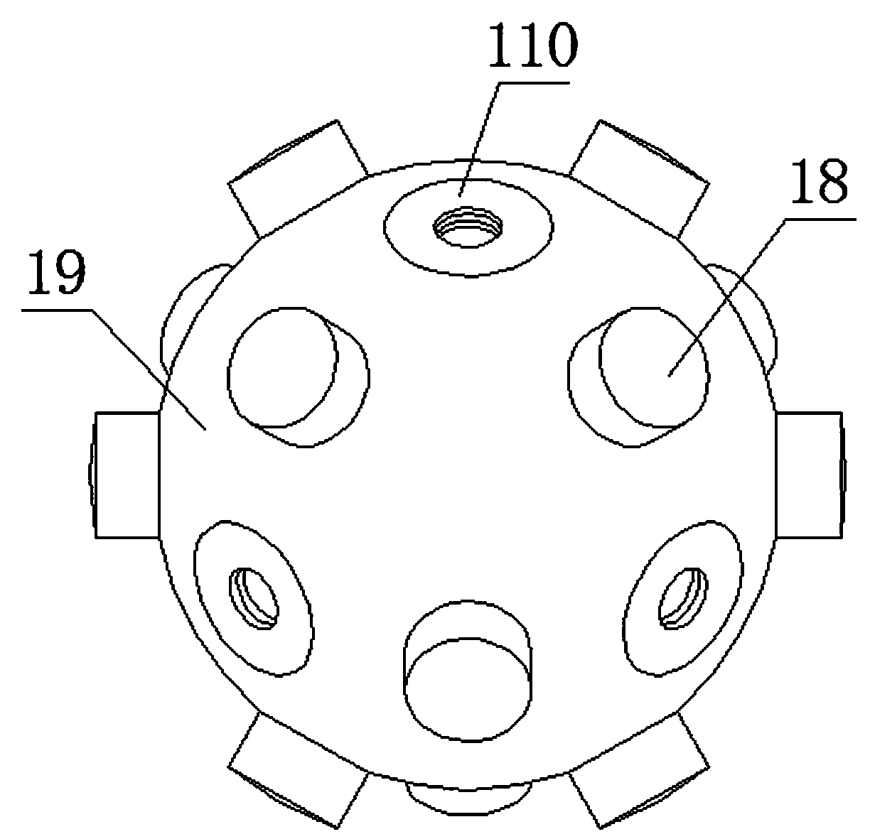
[0033] When implementing on a polyhedron machining center, the support plate 2 is installed on the machining center workbench, and due to the diversity of the drive shaft moving parts of the polyhedron machining center, the movement of the various directions of the three-dimensional sliding table 3 is adjusted so that the detection arm 13 protruding end can be adjusted. The rigid fixation with the moving parts of the machining center can also be fixed by adding the necessary tooling. By setting the moving speed and stroke of the moving parts of the machining center at different positions, and simultaneously controlling the sliding of the three-dimensional sliding table 3 in the horizontal moving direction, the moving speed and stroke of the detector 1 are kept consistent with the moving parts of the machining center, and the movement in the machining center During the moving process of the parts, the piezoelectric ceramic sheets will generate piezoelectric signals. Through the ...


PUM


Abstract

The invention discloses a moving part repeated positioning precision detector, and belongs to the field of machine tool precision measurement. The moving part repeated positioning precision detector comprises an upper carrier module and a lower carrier module, wherein an upper hemispherical groove is formed in the center of the upper carrier module, a lower hemispherical groove is formed in the center of the lower carrier module, the upper hemispherical groove and the lower hemispherical groove are buckled to form a spherical containing space, a sensing ball body is arranged in the spherical containing space, a plurality of piezoelectric ceramic pieces are uniformly pasted on the surface of the sensing ball body, three detection arms which are arranged in the radial direction are arrangedon the sensing ball body, the three detection arms extend out of the upper carrier module and the lower carrier module and are distributed in the X, Y and Z coordinate axes in space, and the upper carrier module and the lower carrier module are correspondingly provided with semi-circle through grooves used for allowing the detection arms to penetrate therethrough. According to the detector, the piezoelectric ceramic pieces in the multiple angles can reflect the fluctuation quantity of a tested tool in all directions in real time, the detection is not limited to fluctuation in three directionsany longer, and then the measured data are more targeted.

Description

technical field [0001] The invention belongs to the field of machine tool accuracy measurement, and in particular relates to a moving part repeat positioning accuracy detector, which can detect the repeat positioning accuracy of the moving parts on various types of machine tools. Background technique [0002] In the machine tool processing system, the accuracy of the tool tip motion trajectory is the key factor affecting the machining accuracy of the workpiece surface. Whether it is a single-axis or multi-axis system, the verification of the repetitive positioning accuracy of the kinematic mechanism driving the tool is to ensure the repetitive positioning accuracy of the machine tool. key to reliability. The number of drive shafts of the existing machine tool moving parts and the motion state mainly include: single-axis motion (linear motion, rotation and compound motion) and multi-axis space linkage compound motion. Regardless of the motion state, due to the limitations of ...

Claims


Application Information

Patent Timeline
Patent Type & Authority Patents(China)
IPC IPC(8): B23Q17/00
Inventor 赵武张全斌荆双喜黄丹
Owner HENAN POLYTECHNIC UNIV
Learn More