An automatic centrifugal pretreatment device and method for water quality detection
A pretreatment device and automatic centrifugation technology, which is used in the preparation of test water, material inspection products, and test samples, etc., can solve problems such as shortage and reduce turbidity of water samples, achieve short time-consuming cycle, ensure quality, and improve The effect of detection accuracy
- Summary
- Abstract
- Description
- Claims
- Application Information
AI Technical Summary
Problems solved by technology
Method used
Image
Examples
Embodiment 1
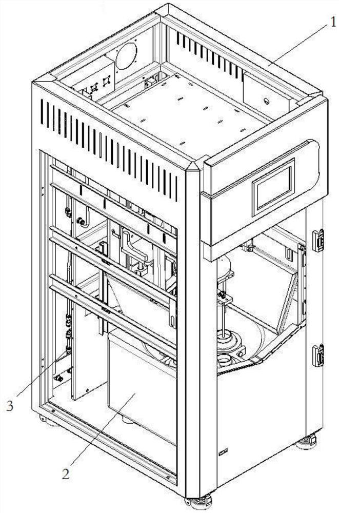
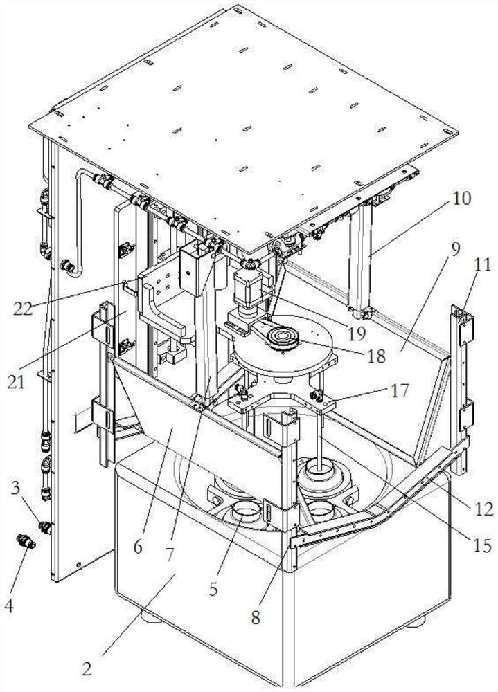
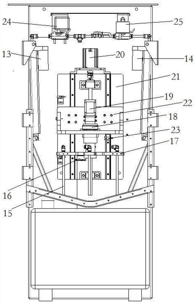
[0049] Such as figure 1 , 2 , 3, 6, and 7, an automatic centrifugal pretreatment device for water quality detection, including a casing 1, a centrifuge 2, a water inlet pipe 3, a water outlet pipe 4, a centrifugal cup 5, a left cover door 6, and a left power rod 7 , left chute 8, right cover door 9, right power lever 10, right chute 11, down chute 12, left cylinder 13, right cylinder 14, connecting pipe 15, position sensor 16, rotating plate 17, pulley 18, Rotating machine 19, lifter 20, fixed plate 21, lifting plate 22, height sensor 23, water outlet pump 24 and water inlet pump 25, inside the shell 1, the water inlet pipe 3, the water outlet pipe 4, the left power rod 7, and the left chute are fixed by bolts 8. Right cover door 9, right power rod 10, right chute 11, left cylinder 13, right cylinder 14 and fixed plate 21, water inlet pipe 3 communicates with water inlet pump 25 through pipelines, and water inlet pump 25 is connected in parallel with metering cup water inlet ...
Embodiment 2
[0052] This embodiment is basically the same as Embodiment 1, the difference is: as figure 1 , 4 , shown in 6, in embodiment 2, cancel left power bar 7, left chute 8, right power bar 10, right chute 11, down chute 12, left cylinder 13 and right cylinder 14, be fixed on shell 1 bottom instead Left rotary motor 26 and right rotary motor 27 at two ends, left rotary motor 26, right rotary motor 27 are connected with left cover door 6, right cover door 9 by rotating shaft, during work, left rotary motor 26 and right rotary motor 27 are driven by rotation The left cover door 6 and the right cover door 9 rotate.
Embodiment 3
[0054] This embodiment is basically the same as Embodiment 1, the difference is: as figure 1 , 5 , shown in 6, in embodiment 2, cancel left power bar 7, left chute 8, right power bar 10, right chute 11, down chute 12, left cylinder 13 and right cylinder 14, be fixed on shell 1 bottom instead Rotating motor 28 and chute 29, rotating motor 28 is connected with left cover door 6 by rotating shaft, and left cover door 6 is connected with right cover door 9 by rotating shaft, and right cover door 9 other ends are connected chute 29 by pulley, during work, The rotation of the rotating motor 28 drives the left cover door 6 to rotate and then the right cover door 9 moves linearly along the chute 29 .
PUM
 Abstract
Description
Claims
Application Information
 - R&D
- Intellectual Property
- Life Sciences
- Materials
- Tech Scout
- Unparalleled Data Quality
- Higher Quality Content
- 60% Fewer Hallucinations
Browse by: Latest US Patents, China's latest patents, Technical Efficacy Thesaurus, Application Domain, Technology Topic, Popular Technical Reports.
© 2025 PatSnap. All rights reserved.Legal|Privacy policy|Modern Slavery Act Transparency Statement|Sitemap|About US| Contact US: help@patsnap.com


