
Energy-saving continuous automatic water and oil separating device

A water-oil separation and energy-saving technology, applied in the field of mechanical equipment, can solve the problems of incomplete drainage, slow separation, and poor practicability, and achieve the effects of low production cost and simple structure.

Pending Publication Date: 2019-05-14
HUBEI UNIV OF TECH
View PDF8 Cites 1 Cited by
  • Summary
  • Abstract
  • Description
  • Claims
  • Application Information

AI Technical Summary

Problems solved by technology

There are some problems in the above three methods: method ① the separation speed is extremely slow, the separated oil contains water and needs to be filtered many times, the service life of the linoleum is short, and the replacement of the linoleum will cause environmental pollution and poor continuity; method ② is very easy to operate Water is brought out during oil absorption, a vacuum pump is required, it cannot be continuous, and the oil layer with strong volatility has a large loss; method ③ is easy to cause excessive drainage or incomplete drainage, and continuous production cannot be carried out
For example: Chinese invention patents "a water-oil separation device" (CN107916173A), "an oil-absorbing tool" (CN108217809A), "oil-water separation device" (CN104147812B) and "an oil-water separation device and its method based on density difference" (CN109354118A) and other disclosed technical solutions, their common defect is that more water is still entrained in the separated oil, and the practicability is not strong

Method used


Image

  • Energy-saving continuous automatic water and oil separating device
  • Energy-saving continuous automatic water and oil separating device

Examples


Embodiment Construction

[0022] The embodiments of the present invention will be further described below in conjunction with the accompanying drawings. Examples of the embodiments are shown in the accompanying drawings, wherein the same or similar symbols throughout represent the same or similar elements or elements with the same or similar functions. The embodiments described below by referring to the accompanying drawings are exemplary and are intended to explain the present invention, but should not be construed as limiting the present invention. Any modifications, equivalent replacements or Improvements, etc., should be included within the scope of the claims of the present invention, and those not described in detail in this technical solution are all known technologies.

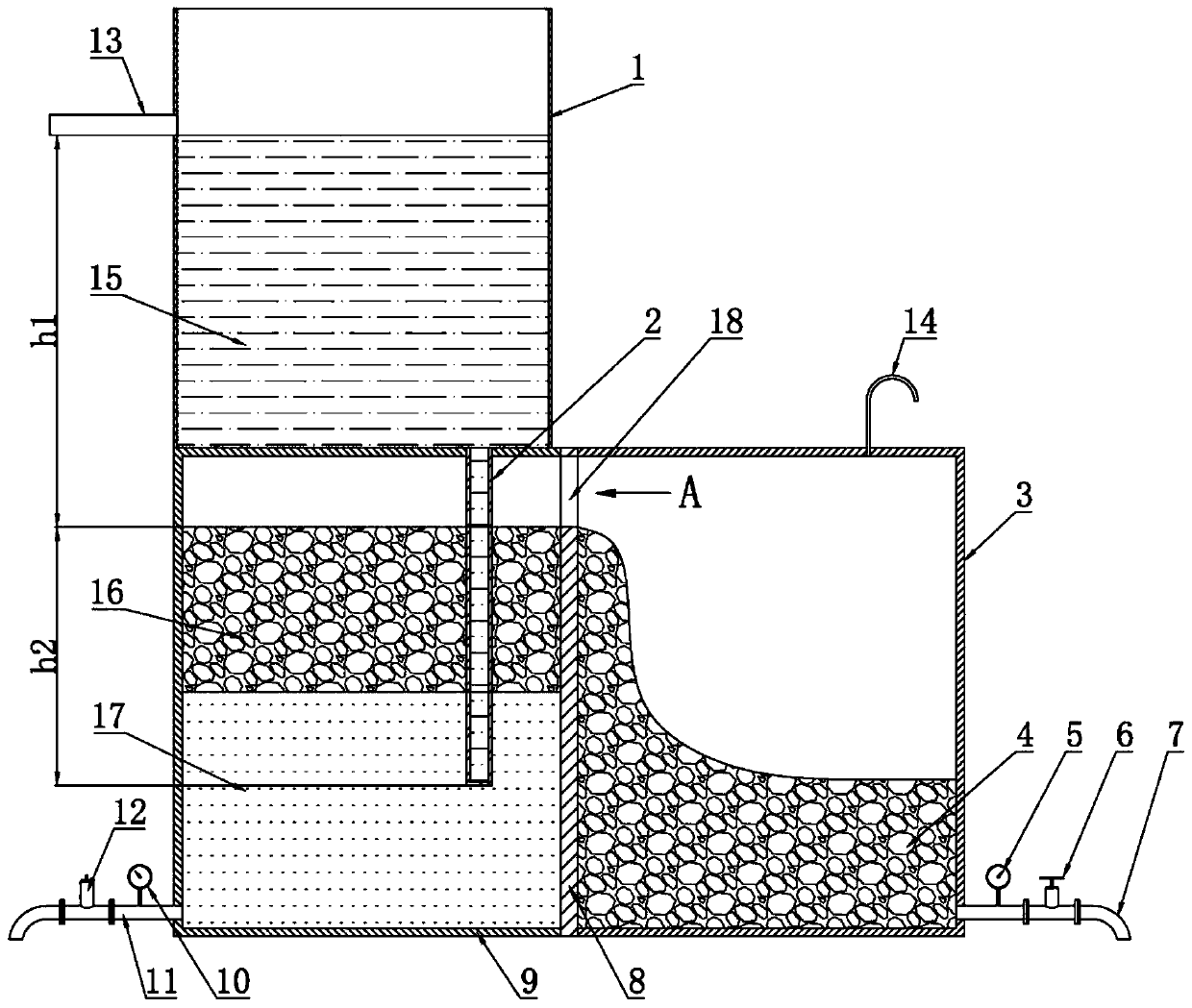
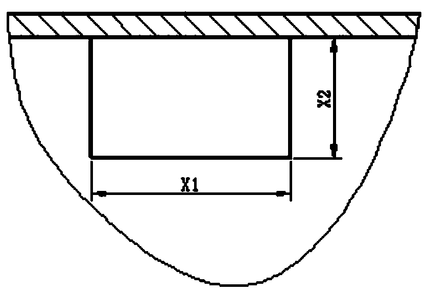
[0023] see Figure 1 ~ Figure 2 , an energy-saving continuous automatic water-oil separation device of the present invention; comprising: an oil-water collection tank 1, an oil tank 3 and an oil-water separation bin 9; the oil ...


PUM


Abstract

The invention discloses an energy-saving continuous automatic water and oil separating device. The energy-saving continuous automatic water and oil separating device comprises an oil and water collection groove, an oil groove and an oil and water separating bin, wherein the oil and water collection groove is formed in the upper part, the oil groove and the oil and water separating bin are formed in the lower part and horizontally placed in parallel; a bin partition plate is arranged between the oil groove and the oil and water separating bin; an overflow hole is formed in the upper part of thebin partition plate; an oil draining pipe is arranged at the lower part of the oil groove; a water draining pipe is arranged at the lower part of the oil and water separating bin; and the oil and water collection groove is used for collecting and storing a oil and water mixed liquid to be treated. A downcomer is arranged on one side of the bottom of the oil and water collection groove; an electric contact oil pressure gauge and an electrically controlled oil draining valve are arranged on the oil draining pipe; and an electric contact water pressure gauge and an electrically controlled pressure limiting valve are arranged on the water draining pipe. By using a gravity force, the mixed liquid is conveyed to the bottom of the separating bin, oil with smaller density automatically floats, the water with large density remains at the bottom, oil liquid drops floating to the top move into the oil groove in one direction, the electric control valve can realize automatic water draining and oil draining at a set pressure, artificial attendant is not needed, and the operation cost is low; and the energy-saving continuous automatic water and oil separating device disclosed by the invention has the advantages of simple structure, low making cost and high promotion value.

Description

technical field [0001] The invention relates to an energy-saving continuous automatic water-oil separation device, which is used in environmental protection engineering, chemical engineering, and mechanical processing industries, and specifically relates to a mutually incompatible liquid separation device, which belongs to the technical field of mechanical equipment. Background technique [0002] In the lubricating oil recovery devices of chemical engineering, environmental protection engineering and mechanical processing equipment, water-oil separation devices are often used. The most common separation methods used by the water-oil separation devices used in them are: ① multi-layer linoleum filter to remove water; ② static Set layers and then absorb the upper layer of oil under negative pressure; ③Stationary layers and then discharge the lower layer of water to obtain the oil layer in three ways. There are some problems in the above three methods: method ① the separation sp...

Claims


Application Information

Patent Timeline
Patent Type & Authority Applications(China)
IPC IPC(8): B01D17/025B01D17/032C10M175/00C10M175/04
Inventor 黄劲松袁钊涵
Owner HUBEI UNIV OF TECH
Learn More