
Pressure measurement module and packaging method thereof

A technology of measurement module and packaging method, which is applied in the direction of measuring device, fluid velocity measurement, velocity/acceleration/shock measurement, etc., which can solve the problem that the packaging mode cannot meet new application requirements, and it is difficult to realize complex electrical circuit layout, packaging and assembly process Complications and other issues, to achieve the effect of protecting normal and stable work, simplifying the process of packaging and assembly, and compact structure

Active Publication Date: 2021-08-31
UNITED AUTOMOTIVE ELECTRONICS SYST
View PDF0 Cites 0 Cited by
  • Summary
  • Abstract
  • Description
  • Claims
  • Application Information

AI Technical Summary

Problems solved by technology

[0004] One is that the package structure can only package one MEMS sensing element. This is because it is electrically interconnected through a metal frame, and it is difficult to realize the layout of complex electrical circuits, so it is difficult to integrate additional components. In addition, the internal The ASIC (Application Specific Integrated Circuit) can only process one pressure signal, so it can only be used to measure one external pressure;
[0005] The second is that it is difficult to integrate passive devices such as capacitors and resistors in this packaging structure. The specific reasons are the same as above. As a result, its integration level is low, and its EMC performance cannot be guaranteed. Moreover, it is necessary to integrate related passive devices in the lower-level packaging. Complicates the subsequent packaging and assembly process
[0006] Obviously, the traditional packaging mode can no longer meet the new application requirements

Method used


Image

  • Pressure measurement module and packaging method thereof
  • Pressure measurement module and packaging method thereof
  • Pressure measurement module and packaging method thereof

Examples


Embodiment Construction

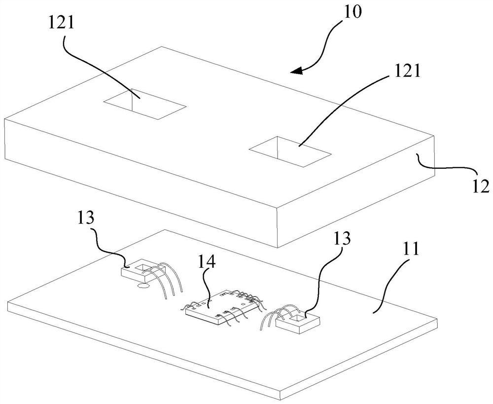
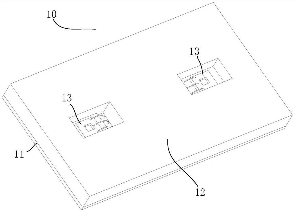
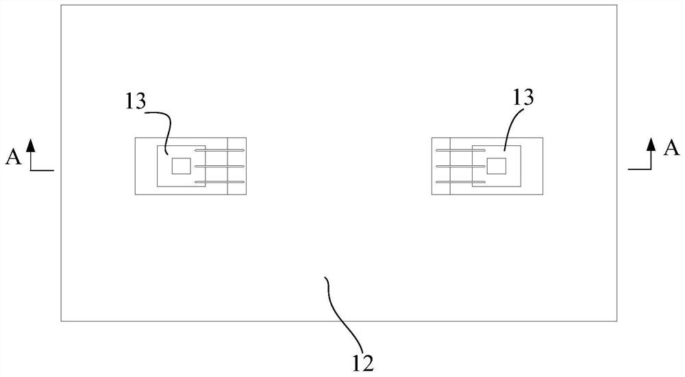
[0055] Embodiments of the present invention are described below through specific examples, and those skilled in the art can easily understand other advantages and effects of the present invention from the content disclosed in this specification. The present invention can also be implemented or applied through other different specific implementation modes, and various modifications or changes can be made to the details in this specification based on different viewpoints and applications without departing from the spirit of the present invention. It should be noted that the diagrams provided in this embodiment are only schematically illustrating the basic idea of ​​the present invention, and only the components related to the present invention are shown in the diagrams rather than the number, shape and shape of the components in actual implementation. Dimensional drawing, the type, quantity and proportion of each component can be changed arbitrarily during actual implementation, ...


PUM


Abstract

The invention relates to a pressure measurement module and its packaging method, which includes a substrate, two MEMS sensing elements, an application specific integrated circuit chip and a passive device, and realizes injection molding packaging through an epoxy resin matrix, which not only has a high degree of integration, but also has a compact structure. With low cost and good EMC performance, it also simplifies the subsequent packaging and assembly process, especially realizes the measurement of two-way pressure signals, and meets various measurement requirements of users. ASICs and passive devices are fixed on the substrate and electrically connected to the substrate. The epoxy resin matrix is ​​placed on the substrate to wrap the ASIC chip and passive devices. The two MEMS sensing elements are fixed on the epoxy On the resin matrix and electrically connected to the substrate, the ASIC chip is respectively connected to two MEMS sensing elements, and the two MEMS sensing elements respectively sense the pressure information of the measurement medium and feed back to the ASIC chip, and the ASIC chip Digitally process the received two-way pressure information.

Description

technical field [0001] The invention relates to the technical field of pressure measurement, in particular to a pressure measurement module and a packaging method thereof. Background technique [0002] In pressure measurement, MEMS (Microelectro Mechanical Systems: microelectromechanical systems) pressure sensors are more and more widely used in industrial, medical and automotive electronics due to their advantages such as wide measurement range, good response characteristics, small size and low price. . However, it is difficult for MEMS components to be directly interconnected with the outside world. It is generally necessary to establish a mechanical and electrical connection with the outside through a packaging structure. At the same time, the packaging structure can also protect the MEMS components. [0003] The inventors have found that the structure currently used for packaging pressure sensors is usually SO packaging (including SOP packaging and SOIC packaging), howe...

Claims


Application Information

Patent Timeline
IPC IPC(8): B81B7/00B81B7/02B81C1/00
Inventor 高奇帅孙晓庆李希彬高立明刘阳
Owner UNITED AUTOMOTIVE ELECTRONICS SYST
Features
  • Generate Ideas
  • Intellectual Property
  • Life Sciences
  • Materials
  • Tech Scout
  • Unparalleled Data Quality
  • Higher Quality Content
  • 60% Fewer Hallucinations
Learn More