Liquid volume reduction device and energy saving and emission reduction type machining water treatment system

A water treatment system, energy saving and emission reduction technology, applied in water/sewage treatment, water/sewage multi-stage treatment, water/sludge/sewage treatment, etc. Workpiece quality and other issues, to achieve good environmental friendliness, avoid rust and corrosion of the workpiece, and reduce the difficulty of handling

Pending Publication Date: 2019-05-14
TAKAHASHI METAL MFG SUZHOU
View PDF0 Cites 0 Cited by
  • Summary
  • Abstract
  • Description
  • Claims
  • Application Information

AI Technical Summary

Problems solved by technology

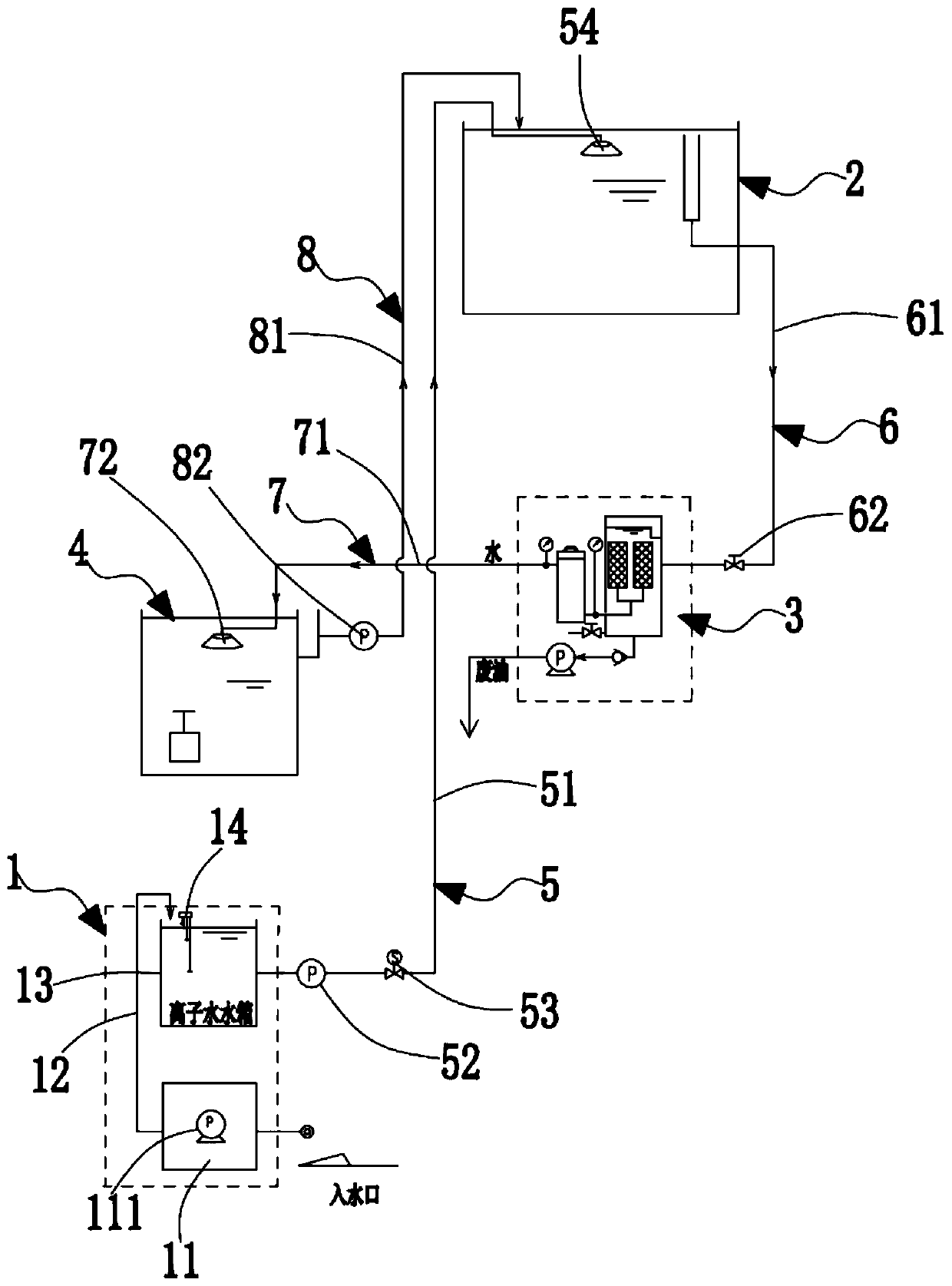
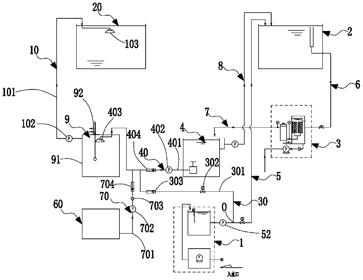
[0003] In the traditional metal cutting machining industry, the products after cutting often need to be cleaned in a washing machine to remove oil, cutting chips and cutting fluid on the workpiece. The sewage (including oil, cutting fluid, etc.) ) are often directly treated as wastewater without sufficient reuse, resulting in a great waste of water resources and more environmental pollution, and the environmental friendliness is not good; even some companies will separate oil from water after cleaning, but The capacity of the separated oil-water solution is still relatively large, and it is necessary to further reduce the capacity of the waste liquid. The existing volume reduction device is mainly used for volume reduction of solid waste, and extrusion, drying, etc. are usually used to reduce the volume of waste. For volume reduction of liquids, there is little related technology
[0004] In addition, the water body used for cleaning usually directly adopts ordinary tap water, and ordinary tap water often contains more chloride ions, which can easily lead to rust and corrosion of the workpiece and affect the quality of the workpiece
[0005] At the same time, the cutting fluid in the machining process is often mixed with ordinary tap water and high-concentration cutting fluid and diluted to a certain concentration before use. Chloride ions in the water also cause the problem of rust and corrosion of the workpiece.

Method used


Image

  • Liquid volume reduction device and energy saving and emission reduction type machining water treatment system
  • Liquid volume reduction device and energy saving and emission reduction type machining water treatment system
  • Liquid volume reduction device and energy saving and emission reduction type machining water treatment system

Examples


Embodiment Construction

[0036] Objects, advantages and features of the present invention will be illustrated and explained by the following non-limiting description of preferred embodiments. These embodiments are only typical examples of applying the technical solutions of the present invention, and all technical solutions formed by adopting equivalent replacements or equivalent transformations fall within the protection scope of the present invention.

[0037] In the description of the scheme, it should be noted that the terms "center", "upper", "lower", "left", "right", "front", "rear", "vertical", "horizontal", " The orientation or positional relationship indicated by "inner", "outer", etc. is based on the orientation or positional relationship shown in the drawings, and is only for the convenience of description and simplification of description, rather than indicating or implying that the device or element referred to must have a specific orientation , constructed and operated in a particular or...


PUM


Abstract

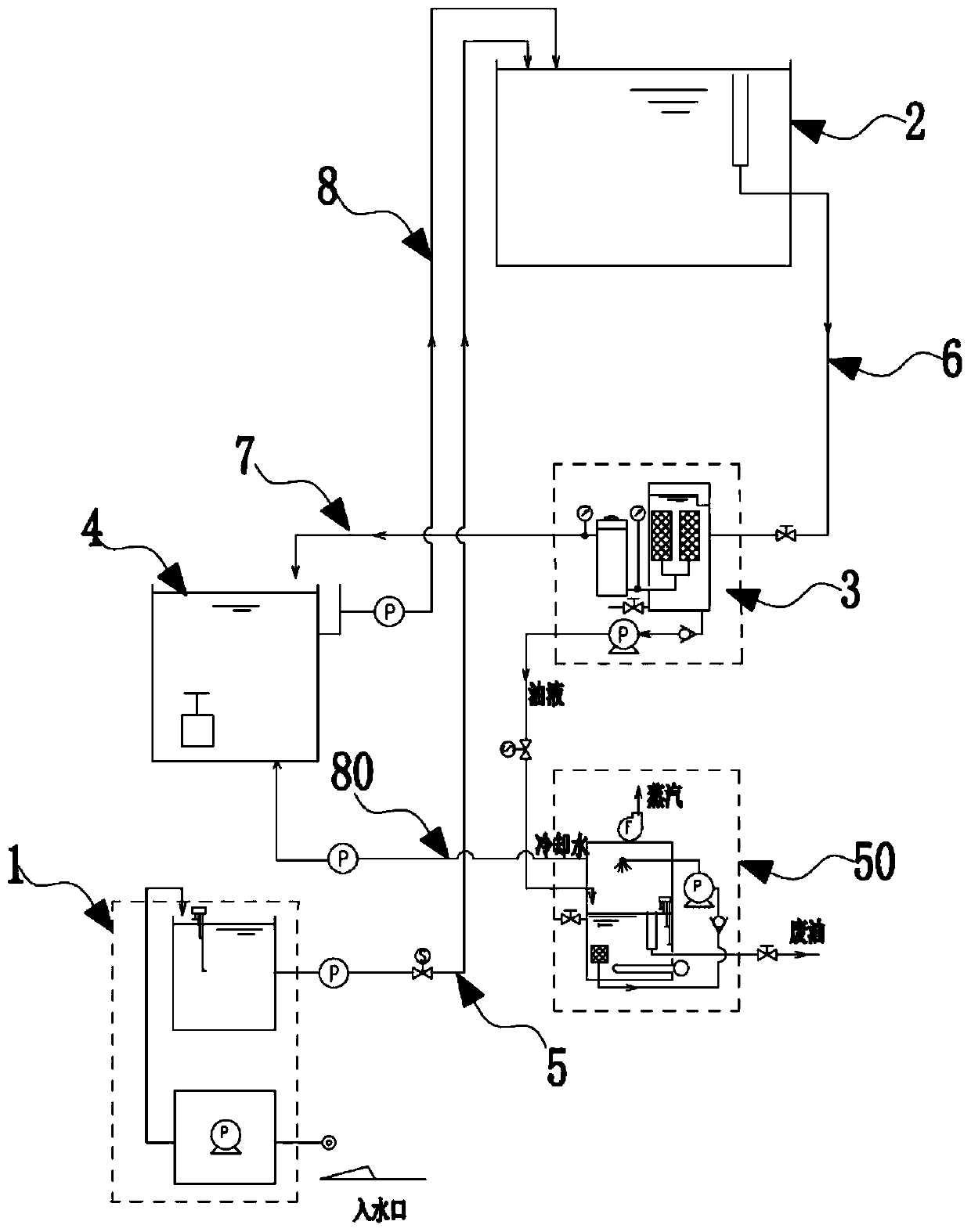
The invention discloses a liquid volume reduction device and an energy saving and emission reduction type machining water treatment system, wherein the liquid volume reduction device comprises a liquid feed pipeline, the liquid feed pipeline is connected with a heating tank, the heating tank heats a liquid in the heating tank through a heater, the heating tank is further provided with a water pumping pipeline connected with a nozzle in an atomizing chamber, the atomizing chamber is connected with an exhaust fan, an air outlet of the exhaust fan is connected with the atmosphere. The scheme usesthe characteristic that liquids of different densities are layered, the waste liquid is heated, then the different substances are layered, the heated water on the lower layer is atomized and discharged, so that the quantity of water in the waste liquid is reduced, the volume of the waste liquid is efficiently reduced, the discharged vapor is directly blended into the atmosphere, no pollution is caused, meanwhile, not like discharging water directly, no extra pipeline needs to be configured to transport, the environmentally friendliness is good, the whole equipment is compact in structure andlow in energy consumption, and the effective implementation means is provided for the volume reduction of the liquid.

Description

technical field [0001] The invention relates to the field of machining equipment, in particular to a liquid volume reduction device and an energy-saving and emission-reducing cutting processing water treatment system. Background technique [0002] Metal cutting, the material removal plus forming method in the metal forming process, still occupies a large proportion of today's machine manufacturing. The metal cutting process is a process in which the workpiece and the tool interact. The tool removes excess metal from the workpiece to be processed, and under the premise of controlling productivity and cost, the workpiece obtains geometric accuracy, dimensional accuracy and surface quality that meet the design and process requirements. [0003] In the traditional metal cutting machining industry, the products after cutting often need to be cleaned in a washing machine to remove oil, cutting chips and cutting fluid on the workpiece. The sewage (including oil, cutting fluid, etc...

Claims


Application Information

Patent Timeline
Patent Type & Authority Applications(China)
IPC IPC(8): C02F1/12C02F9/10C10M175/00C10M175/04
Inventor 高贵焕徐清
Owner TAKAHASHI METAL MFG SUZHOU
Why Eureka
Try Eureka