Combustion chamber structure of cycloid rotor engine and cycloid rotor engine

A rotary engine and combustion chamber technology, applied in combustion engines, machines/engines, internal combustion piston engines, etc., can solve the problems of affecting thermal efficiency, short constant volume combustion time, reducing engine thermal efficiency, etc., to improve thermal efficiency, reduce energy consumption, The effect of improving energy conversion efficiency

Inactive Publication Date: 2019-05-14
王为民
View PDF10 Cites 1 Cited by
  • Summary
  • Abstract
  • Description
  • Claims
  • Application Information

AI Technical Summary

Problems solved by technology

During the rotation of the eccentric shaft through these three stages, if the volume of the combustion chamber changes too much, the thermal efficiency of the engine will be reduced
[0013] Existing cycloid rotor engines such as Figure 25 As shown, the combustion chamber (V2) is set at the center of the arc-shaped chamber, so when the rotor rotates, the equal-volume interval of the slight change in the gap between the rotor lobe and the arc-shaped chamber is not fully used for the combustion of the mixture. The constant volume combustion time is too short, which affects the thermal efficiency

Method used


Image

  • Combustion chamber structure of cycloid rotor engine and cycloid rotor engine
  • Combustion chamber structure of cycloid rotor engine and cycloid rotor engine
  • Combustion chamber structure of cycloid rotor engine and cycloid rotor engine

Examples


Embodiment Construction

[0069] The present invention provides many applicable inventive concepts that can be embodied in numerous specific contexts. The specific examples described in the following embodiments of the present invention are only used as illustrations of specific embodiments of the present invention, and are not intended to limit the scope of the present invention.

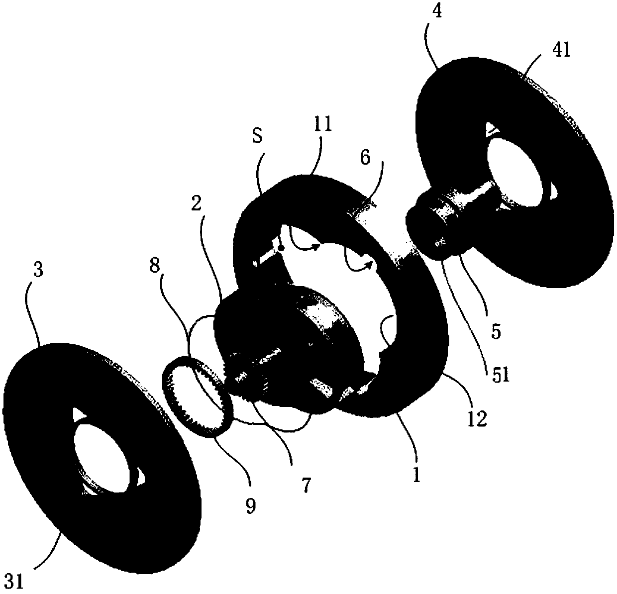
[0070] figure 1 An exploded schematic diagram of the main components of the cycloid rotor engine. Such as figure 1 As shown, the cycloid rotor engine mainly includes a housing 1, a rotor 2, end covers 3, 4, an eccentric shaft 5, and auxiliary mechanisms not shown, such as fuel injection, ignition, suction and exhaust mechanisms. Parts related to the present invention will be described below, and the remaining parts are prior art. Reference can be made to documents such as US Pat.

[0071] The rotor 2 is installed in the inner cavity S of the casing 1, and the two ends of the casing 1 are sealed by end covers 3, 4. The...


PUM


Abstract

The invention discloses a combustion chamber structure of a cycloid rotor engine and the cycloid rotor engine. Three work chambers (S1, S2 and S3) are formed between the radial outer periphery face ofa rotor 2 and the inner periphery face of a shell, a convex peak is formed between every two adjacent work chambers (S1, S2 and S3), two cams are arranged on the radial outer periphery face 24 of therotor 2, the shape of the cams is the same with that of the work chambers (S1, S2 and S3), when the rotor 2 rotates, the radial outer periphery of the rotor 2 is kept contact with the convex peaks 11, and the cams enter in and retreat from the work chambers (S1, S2 and S3) in turn; when the rotor is located on the upper stop points of the work chambers (S1, S2 and S3), a combustion chamber 6 is formed between the radial outer periphery face of the rotor 2 and the inner periphery face of the shell, the combustion chamber is arranged in the opposite direction of the rotating direction of the rotor 2, and deviates from a datum line L1 by a certain angle, and when the rotor 2 is located on the upper stop points, the datum line L1 connects the center 02 of the rotor 2 with the center 01 of aneccentric shaft 5.

Description

technical field [0001] The invention relates to a combustion chamber structure of a cycloid rotor engine, in particular to a combustion chamber structure for improving the work efficiency of the cycloid rotor engine. Background technique [0002] In 1903, American JOHN F. COOLEY proposed Figure 22 The prototype of the cycloidal rotor engine is shown. The prototype uses the rotor to replace the piston in the reciprocating engine. The synchronous gear is used to make the rotor perform planetary motion. gas. It involves multiple technologies such as three-chamber or multi-chamber, eccentric shaft drive, radial seal on the cylinder block, side seal, intake and exhaust channels (air port type, airless valve) and other technologies. [0003] Chinese patent document cn85203161 (Liang Zhiheng, 1985, four-stroke air-ported cycloid rotor engine) discloses a sealing improvement scheme for a four-blade, five-cavity eccentric shaft quincunx-cycloid rotor engine. The sealing system com...

Claims


Application Information

Patent Timeline
Patent Type & Authority Applications(China)
IPC IPC(8): F02B55/14F02B55/02
Inventor 王为民
Owner 王为民
Why Eureka
Try Eureka