A filter material corrosion performance testing device

A test device, a technology for corrosion performance, used in measurement devices, weather resistance/light resistance/corrosion resistance, analyzing materials, etc.

Active Publication Date: 2021-04-23
河南合众电力技术有限公司
View PDF5 Cites 0 Cited by
  • Summary
  • Abstract
  • Description
  • Claims
  • Application Information

AI Technical Summary

Problems solved by technology

[0004] The purpose of the present invention is to provide a filter material corrosion performance test device, to reduce the damage caused by corrosion smoke to the operator when the material is taken out after the test

Method used


Image

  • A filter material corrosion performance testing device
  • A filter material corrosion performance testing device
  • A filter material corrosion performance testing device

Examples


specific Embodiment 1

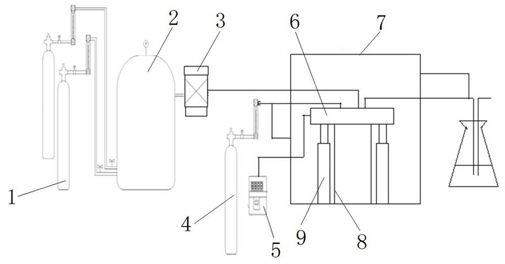
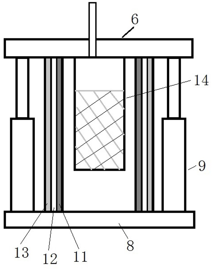
[0023] Such as Figure 1 to Figure 3 As shown, the filter material corrosion performance testing device includes a filter material corrosion system, a flue gas generation system, a flue gas purification system, an exhaust gas collection structure and a computer control system.

[0024] The filter material corrosion system includes a test box. The test box is composed of a box body 8 and a box cover 6. The materials of the box body 8 and the box cover 6 are all stainless steel. The box body 8 has an upward opening, and the box cover 6 is up and down. Direction movement button is installed on the opening of casing 8. An air pressure connecting rod 9 is arranged outside the test box, and the output end of the air pressure connecting rod 9 is fixedly connected with the box cover 6. The box cover 6 can be sealed on the box body 8 and moved up by the box body 8 through the up and down expansion and contraction of the output end. go. The inside of the box cover 6 is fixed with an i...

specific Embodiment 2

[0037] Such as Figure 4 As shown, the difference from the above-mentioned embodiment mainly lies in that only the corrosion fume inlet pipe 3 and the exhaust gas discharge pipe 6 of the test chamber are provided on the test chamber 2, and the purification gas inlet pipe 4 and the exhaust gas of the purification chamber are arranged on the purification chamber 1. Exhaust pipe 5. After the test is completed, only the purified air is filled into the purified box through the purified gas inlet pipe 4, and the cooling step is omitted.

specific Embodiment 3

[0039] Such as Figure 5 As shown, the difference from the above-mentioned embodiment mainly lies in that in this embodiment, the test box includes a box body 2 and a filter material access door 3, wherein the filter material access door 3 is hinged on the box body 2, and the filter material access The rotation of the pick-and-place door 3 can realize the communication between the test box and the clean box 1 . In this embodiment, the purification box 1 also includes a box body and a box cover hinged together. In this embodiment, the driving mechanism may be a mechanism that drives the filter material pick-and-place door 3 to rotate, for example, a motor is provided at the hinge shaft.


PUM


Abstract

The invention provides a device for testing the corrosion performance of filter material, which can reduce the harm caused by corrosion smoke to operators when the material is taken out after the test. The filter material corrosion performance test device includes a test box for placing the filter material. The test box has a corrosion smoke inlet and a filter material pick-and-place door for taking and placing the filter material. The test device also includes a purification chamber for containing the test box. box, the test device also includes a driving mechanism for opening the filter material access door to communicate with the purification box and the test box, and the test device also includes an air filling device for filling the purification box with purified gas after the purification box and the test box are connected. Pipes and discharge pipes for the corrosive fumes and purge gases in the purge box to discharge. The invention can reduce the corrosion smoke concentration at the test box and the filter material after the test is completed, facilitates the operator to perform the material retrieving operation, and reduces the injury to the operator.

Description

technical field [0001] The invention relates to a filter material corrosion performance testing device. Background technique [0002] With the increasing emphasis on energy conservation and emission reduction, the country has increasingly stringent requirements on the emission standards of air pollutants in various industries. In order to meet the requirements of low pollution emission concentration and control the emission of fine dust, more and more industries use bag filter or electric bag composite filter. With the wide application of bag filters in coal-fired power plants, premature corrosion and breakage of core component filter bags occur frequently. [0003] It is very necessary to study the aging and corrosion mechanism of filter bags, solve the problem of short life of filter bag failure and corrosion, and achieve the purpose of maintaining stable operation of bag filters and reducing operating costs. In the prior art, when testing filter materials including filt...

Claims


Application Information

Patent Timeline
Patent Type & Authority Patents(China)
IPC IPC(8): G01N17/00
Inventor 李东梅
Owner 河南合众电力技术有限公司
Why Eureka
Try Eureka