A sampling device for sea area oil pollution

A technology of oil pollution and sampling device, applied in the field of oil, can solve the problems of great influence on the accuracy of research results and easy occurrence, and achieve the effect of improving the accuracy of water sample data and expanding the effect of circulation

Inactive Publication Date: 2020-10-30
徐菲菲
View PDF10 Cites 0 Cited by
  • Summary
  • Abstract
  • Description
  • Claims
  • Application Information

AI Technical Summary

Problems solved by technology

The existing sampling device is generally only a sampling bottle, which obviously has a great influence on the accuracy of the research results, and at the same time, a single sampling bottle is prone to problems during transportation

Method used


Image

  • A sampling device for sea area oil pollution
  • A sampling device for sea area oil pollution
  • A sampling device for sea area oil pollution

Examples


Embodiment 1

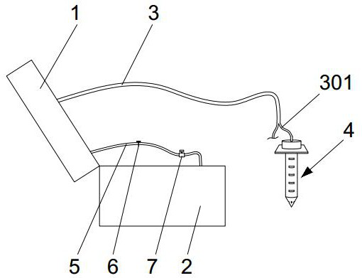
[0025] see Figure 1-6 As shown, the sampling device for sea area oil pollution using new energy includes,

[0026] The sampler 4 has a transfer pipe 5, which is connected to the pump body 8,

[0027] The sampling tube 3 is connected with the pump body 8, and the sampling port of the sampling tube 3 is connected with the Y-shaped tube 301, and

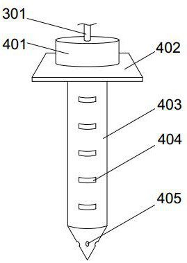
[0028] The sampler 4 is connected to a port of the Y-shaped pipe 301, the sampler 4 includes a connecting body 401 connected to the Y-shaped pipe 301, the bottom of the connecting body 401 is connected to the floating plate 402, and the bottom of the floating plate 402 is connected to the sampling column 403 for sampling The bottom of the sampling column 403 is conical, and a ball cavity 412 is provided inside and at least one solid ball 413 is placed therein. The ball cavity 412 is in contact with the outside through the flow channel 405 . The present invention carries out the water body sampling operation to the sea area where the ...

Embodiment 2

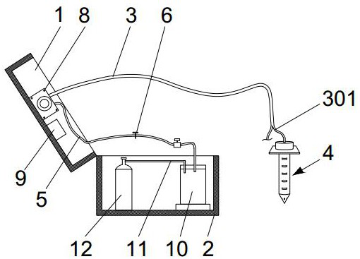
[0037] When the sampling device for sea area oil pollution using new energy sources of the present invention actually works: the sampling device of the present invention is brought to the vicinity of the water area to be collected, the sampler 4 is dropped into the water, and two sampling methods are selected. The first one uses a pump Body 8 and sampling pipe 3 directly extract water samples into the sampling bottle 10 and control the sampling volume through the clamp and valve body 7. At the same time, the nitrogen or oxygen in the gas tank 12 is input into the sampling bottle 10 through the gas delivery pipe 11 according to research needs to ensure The survival of aerobic bacteria or anaerobic bacteria in the sampling bottle 10 ensures the sampling effect; the second is to control the lifting of the lifting column 408 by controlling the on-off or magnetic force of the electromagnet 406 to control the sealing plug 409 The blocking of the sampling port 404 enables the sampling...


PUM


Abstract

The invention discloses a sampling device for petroleum pollution in a sea area adopting new energy. The sampling device for the petroleum pollution in the sea area adopting the new energy comprises asampler and a sampling pipe, wherein the sampler is provided with a transmission pipe, and the transmission pipe is connected with a pump body; the sampling pipe is connected with the pump body, anda sampling opening of the sampling pipe is connected with a Y-shaped pipe; and the sampler is connected with an end port of the Y-shaped pipe. The sampler comprises a connecting body which is connected with the Y-shaped pipe, the lower part of the connecting body is connected with a floating plate, the lower part of the floating plate is connected with a sampling column for sampling, the bottom ofthe sampling column is in a conical shape and is internally provided with a ball cavity, at least one solid ball is placed in the ball cavity, and the ball cavity is in contact with the outside through a fluid flow channel. The sampling device has high stability in water, water layers with different depths can be sampled, the sampling mode is many, and the sampling device for the petroleum pollution in the sea area adopting the new energy has the characteristics of high efficiency and accurate sampling.

Description

technical field [0001] The invention relates to the field of petroleum technology, in particular to a sampling device for sea area petroleum pollution using new energy. Background technique [0002] Oil pollution refers to the pollution caused by leakage and discharge of oil during oil extraction, transportation, loading and unloading, processing and use, mainly in the ocean. Oil floats on the sea surface and rapidly spreads to form an oil film, which can be migrated and transformed through diffusion, evaporation, dissolution, emulsification, photodegradation, biodegradation and absorption. The oil can adhere to the gills of the fish, suffocate the fish, inhibit the spawning and hatching of waterfowl, destroy the impermeability of their feathers, and reduce the quality of aquatic products. The formation of oil film can hinder the reoxygenation of water bodies, affect the growth of marine plankton, and destroy the ecological balance of the ocean. In addition, it can also dam...

Claims


Application Information

Patent Timeline
Patent Type & Authority Patents(China)
IPC IPC(8): G01N1/14
Inventor 徐菲菲叶云
Owner 徐菲菲
Why Eureka
Try Eureka