Construction method and device for cast-in-place concrete pile

A construction method and concrete technology, applied in sheet pile wall, foundation structure engineering, construction and other directions, can solve the problems of disturbed undisturbed soil, poor actual controllability, increased construction difficulty, etc., to reduce project cost, reduce settlement difference, The effect of shortening the construction period

Active Publication Date: 2019-05-21
祝波 +1
View PDF6 Cites 6 Cited by
  • Summary
  • Abstract
  • Description
  • Claims
  • Application Information

AI Technical Summary

Problems solved by technology

Compared with conventional bored piles, the above process is effective in improving the bearing capacity of single piles, reducing pile foundation settlement, and reducing engineering costs, but it also has obvious defects. For the simple cutting and expanding process , the cutting process disturbs the undisturbed soil around the disc cavity, and after forming the disc, when the disc is stressed, it is easy to cause a large settlement deformation of the disc body, which leads to the settlement deformation of the pile body
For extruded and expanded branch-disc piles, the first choice is that the branches and discs are formed by multiple corners and superimposed extrusion, and there is a possibility that the soil will be squeezed into the previous completed cavity during the second and subsequent extrusion and expansion. , and the integrity and quality of the disk are doubtful, the existing detection methods cannot effectively detect the integrity and quality of the disk, and, for the test results of individual branches and disks, it is impossible to determine whether it is a branch or a disk; Secondly, two sets of equipment are required for the two processes of drilling and extrusion, and there are problems such as increased construction difficulty, low process efficiency, and inability to strengthen the frictional resistance of piles at unextruded parts.
For the grouting process at the bottom of the pile and around the pile, its actual controllability is poor. Not only the actual diffusion range and direction of the grout cannot be controlled and guaranteed, but the uniformity of the grouting result is fundamentally uncontrollable and guaranteed. The result is quite The bearing capacity and settlement deformation of adjacent piles are highly discrete

Method used


Image

  • Construction method and device for cast-in-place concrete pile
  • Construction method and device for cast-in-place concrete pile
  • Construction method and device for cast-in-place concrete pile

Examples


Embodiment 1

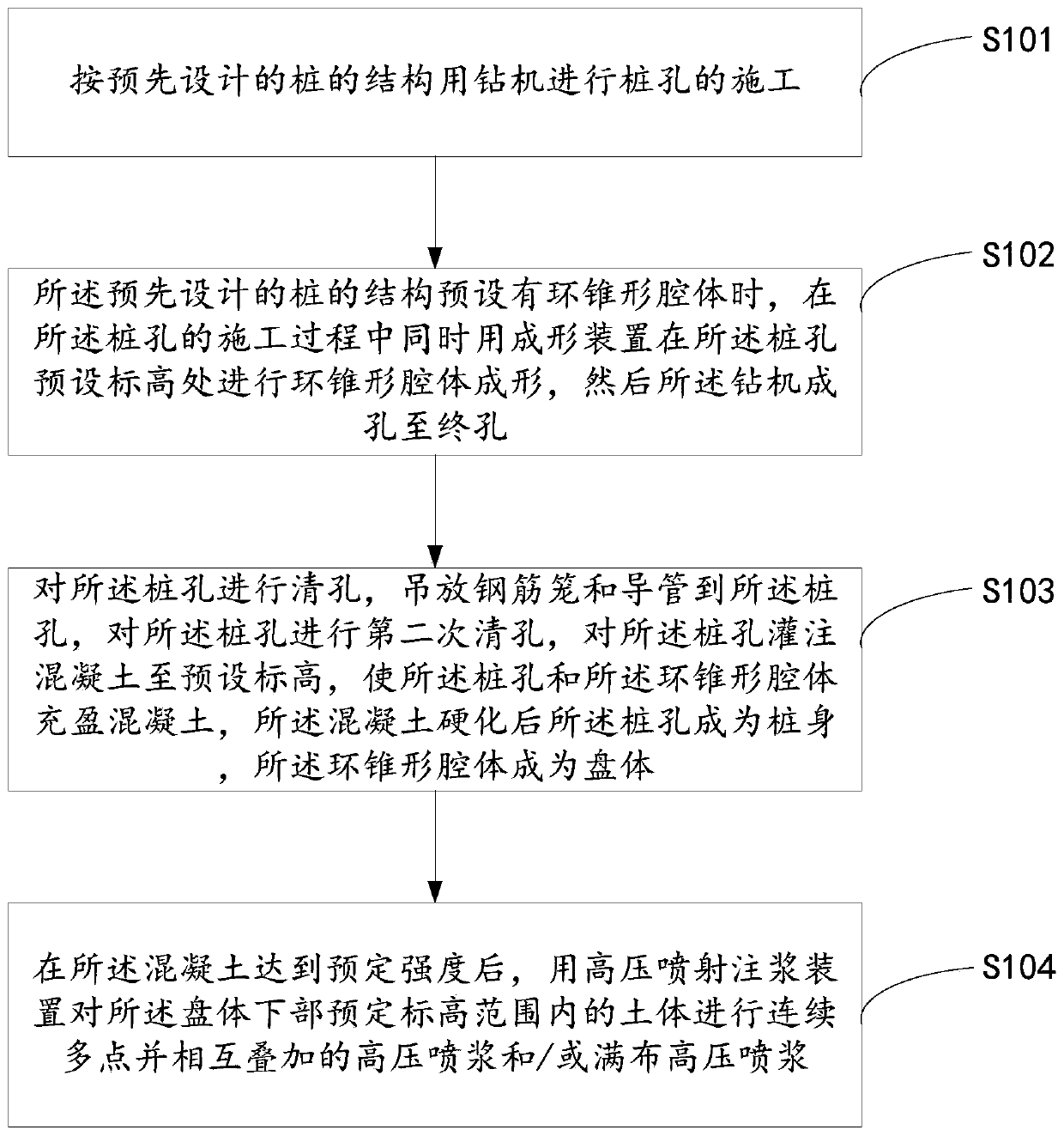
[0039] refer to figure 1 , a construction method for concrete pouring piles, comprising:

[0040] S101. Use a drilling rig to construct pile holes according to the pre-designed pile structure.

[0041] Before constructing the pile hole with a drilling rig according to the pre-designed pile structure, continuous multi-point and superimposed high-pressure spray grouting is implemented in advance within the predetermined height range at the preset elevation of the pile hole, and the cement soil within the height range reaches After presetting the strength, use a drilling rig to construct pile holes according to the pre-designed pile structure.

[0042] According to the pre-designed pile structure, the process of pile hole positioning, burying casing and drilling rig placement before hole formation is carried out.

[0043] The hole-forming process of the drilling rig is drilling with mud retaining walls or other forms of non-mud retaining walls; the drilling rig is an integrated...

Embodiment 2

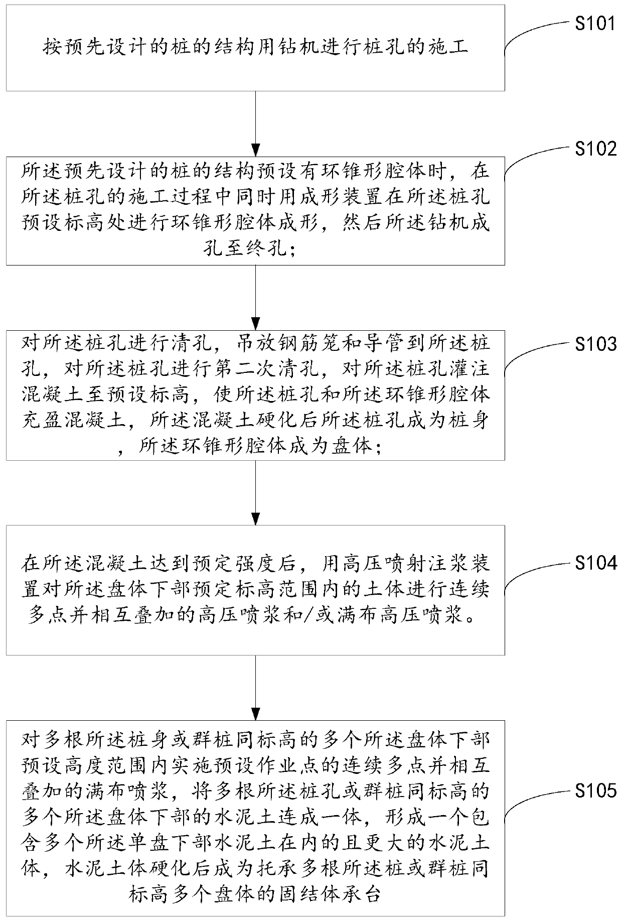
[0057] refer to figure 2 , this embodiment adds the following steps on the basis of Embodiment 1:

[0058] S105. Implement continuous multi-point preset operation points within the predetermined height range of the lower part of the plurality of trays of the same elevation of the plurality of piles or pile groups and spray grouting on each other, and place the plurality of piles The pile body or the pile group is integrated with the cement soil at the lower part of the plurality of trays at the same level to form a larger cement soil body including the cement soil at the lower part of the single tray. After the cement soil hardens It becomes a consolidated body cap supporting a plurality of piles with the same elevation as a plurality of plates.

[0059] For multiple piles or pile groups, continuous multi-point superimposed high-pressure shotcrete can be implemented within the preset height range of the lower parts of multiple plates of the same elevation according to the pr...

Embodiment 3

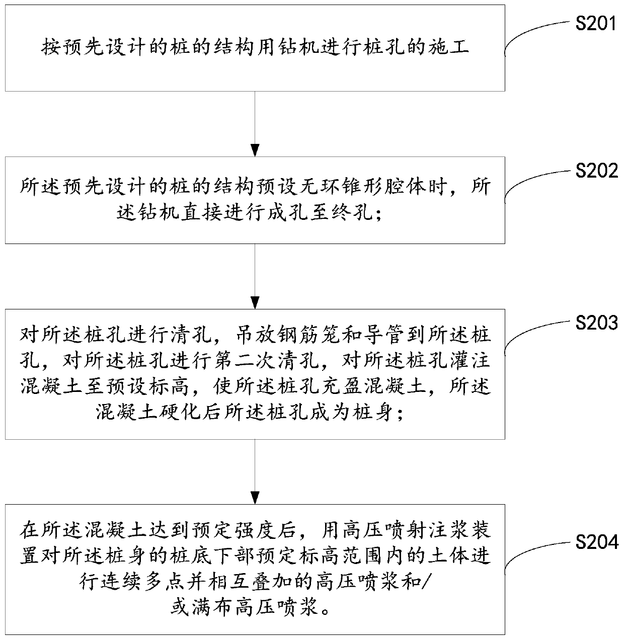
[0061] refer to image 3 , a construction method for concrete pouring piles, comprising:

[0062] S201. Use a drilling machine to construct pile holes according to the pre-designed pile structure.

[0063] According to the pre-designed pile structure, the process of pile hole positioning, burying casing and drilling rig placement before hole formation is carried out.

[0064] The hole-forming process of the drilling rig is drilling with mud retaining walls or other forms of non-mud retaining walls; the drilling rig is an integrated device composed of a drilling rig or a drilling rig and a cone-shaped cavity former for pile hole rings, and its control and operation methods are: Automatic or manual operation and control mode.

[0065] S202. When the structure of the pre-designed pile presets a ringless tapered cavity, the drilling machine directly performs hole forming to the final hole.

[0066] The drilling rig drills into the hole until it reaches the design pile bottom el...


PUM


Abstract

The invention discloses a construction method and device for a cast-in-place concrete pile. The technology is characterized in that a preset annular conical cavity is formed in a drilling machine holeforming process; an annular conical cavity with one or more intervals along a pile hole is formed after hole drilling is completed; after hole cleaning, steel reinforcement cage lifting and placing,secondary hole cleaning and concrete pouring are carried out, the pile hole becomes a pile body, and the cavity becomes a disc body. After concrete is poured into the end hole, the pile hole of the preset ring-free conical cavity becomes a pile body; after the concrete reaches the preset strength, continuous multi-point superposition and / or full distribution of high-pressure guniting is carried out within a preset height range of the lower portion of the disc body and / or the lower portion of the pile bottom. Cement soil formed by mixing slurry and a soil body is connected into a whole throughslurry spraying; and after hardening, an integral consolidation body is formed to support a tray body (including a plurality of tray bodies) and / or a pile bottom (including a pile group bottom), so that the bearing capacity of a pile foundation is greatly improved, and sedimentation and differential sedimentation are remarkably reduced.

Description

【Technical field】 [0001] The invention relates to a construction method of concrete pouring piles in the field of civil engineering, in particular to a pile body provided with a single or a plurality of discs, and under the discs, when there is no disc, grouting is performed under the bottom of the pile in a high-pressure jetting manner to form Concrete pouring piles for load-bearing platforms. 【Background technique】 [0002] In order to overcome the problem that the bottom sediment of conventional bored concrete piles is difficult to handle and the frictional resistance of the mud skin interlayer around the pile body is low, the expansion / support pile technology and pressure grouting at the pile bottom and around the pile appeared in the civil engineering practice. Craftsmanship etc. Compared with conventional bored piles, the above process is effective in improving the bearing capacity of single piles, reducing pile foundation settlement, and reducing engineering costs, b...

Claims


Application Information

Patent Timeline
IPC IPC(8): E02D5/46
Inventor 裴晓峰祝波
Owner 祝波
Why Eureka
Try Eureka