Intake supercharged fuel engine

A fuel engine and air intake pressurization technology, which is applied to combustion engines, engine components, machines/engines, etc., can solve problems such as affecting air tightness, increasing intake pressure, and affecting discharge frequency, so as to reduce the possibility of deflagration performance, increase the negative pressure of the intake air, and improve the quality of the exhaust gas

Pending Publication Date: 2019-05-21
HUBEI UNIV OF SCI & TECH
View PDF0 Cites 0 Cited by
  • Summary
  • Abstract
  • Description
  • Claims
  • Application Information

AI Technical Summary

Problems solved by technology

[0002] Fuel engines are generally used in traffic equipment such as automobiles. Those skilled in the art know that the fuel supply of fuel engines (especially gasoline engines) is determined according to the intake air near the fuel injector. The larger the intake air, the greater the torque of the engine. In the prior art, the turbocharger method is used to increase the intake pressure at an appropriate time or under all working conditions, thereby increasing the engine torque. The turbocharger uses the exhaust gas pressure as the power source, and the exhaust pipe The exhaust gas turbine installed at the exhaust gas turbine is connected with the intake turbine installed at the intake manifold to make them synchronized, and the exhaust gas pressure is used to drive the intake turbine to rotate to increase the intake pressure at the intake manifold. Although this method is mature , but it also brings certain side effects and defects, such as the increase of exhaust gas exhaust resistance, resulting in incomplete exhaust exhaust, more exhaust gas residues in the combustion chamber, the negative pressure of the intake air in the combustion chamber is affected, and more combustion residues. There is a lot of carbon deposits. Although the exhaust gas recirculation is benef

Method used


Image

  • Intake supercharged fuel engine
  • Intake supercharged fuel engine
  • Intake supercharged fuel engine

Examples


Embodiment Construction

[0023] The following are specific embodiments of the present invention and in conjunction with the accompanying drawings, the technical solutions of the present invention are further described, but the present invention is not limited to these embodiments.

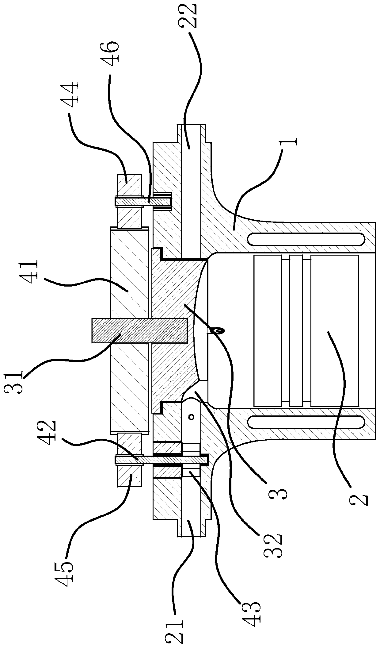
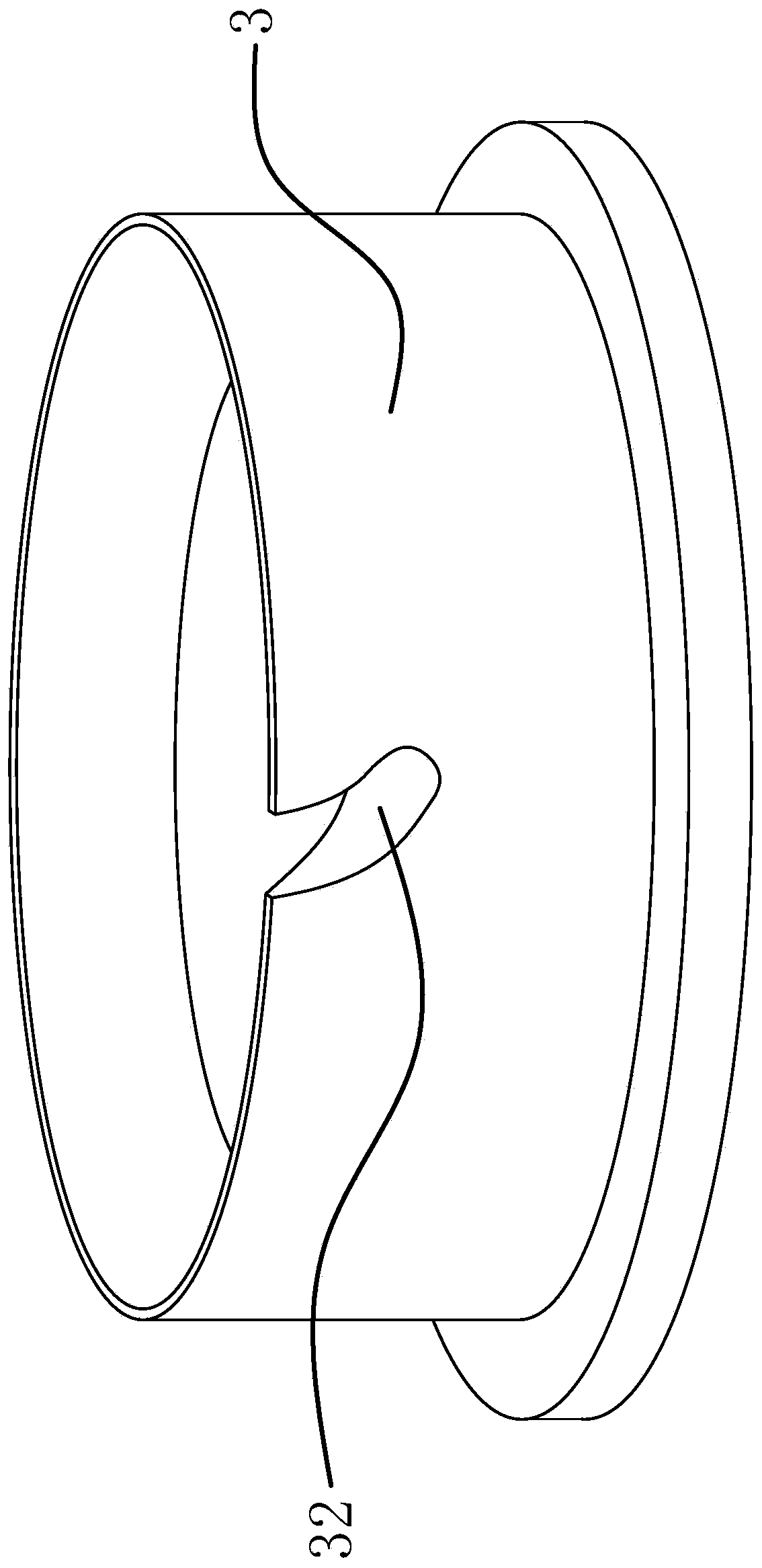
[0024] Such as figure 1 and figure 2 As shown, the fuel engine includes a cylinder block 1, a piston 2 slidingly connected in the cylinder block 1, and a crankshaft hinged with the piston 2. Gas manifold hole 22, the top opening of cylinder block 1, there is a rotor 3 rotatably connected to cylinder block 1 at the top opening of cylinder block 1, the inner wall surface of cylinder block 1, the top surface of piston 2 and the bottom surface of rotor 3 form the combustion chamber of the engine. The center of the rotor 3 is fixedly connected with a shaft 31, the shaft 31 is synchronized with the crankshaft, and the rotor 3 is provided with a gap 32 that runs through the bottom wall of the rotor 3, and the gap 32 can communi...


PUM


Abstract

The invention provides an intake supercharged fuel engine, and belongs to the technical field of vehicles. The fuel engine comprises an intake hole and an exhaust hole formed in a cylinder block; thetop of the cylinder block is opened; a rotor rotationally connected to the cylinder block is arranged in the top opening of the cylinder block; the inner wall surface of the cylinder block, the top surface of a piston and the bottom surface of the rotor form a combustion chamber of the engine; the rotor is provided with a gap penetrating through the bottom wall surface of the rotor; the gap can communicate the intake hole with the combustion chamber or communicate the exhaust hole with the combustion chamber; a transmission gear is fixedly arranged on a rotating shaft; the cylinder block is rotationally connected with an intake supercharging shaft; the intake supercharging shaft is connected with a supercharging gear engaged with the transmission gear; and the intake supercharging shaft isprovided with an intake turbine positioned in the intake hole and capable of urging air currents in the intake hole to flow to the combustion chamber when the intake supercharging shaft and the transmission gear are opposite in rotating direction. The fuel engine has the advantages of capability of improving the intake quantity and the like.

Description

technical field [0001] The invention belongs to the technical field of automobiles, and relates to an air intake supercharging type fuel engine. Background technique [0002] Fuel engines are generally used in traffic equipment such as automobiles. Those skilled in the art know that the fuel supply of fuel engines (especially gasoline engines) is determined according to the intake air near the fuel injector. The larger the intake air, the greater the torque of the engine. In the prior art, the turbocharger method is used to increase the intake pressure at an appropriate time or under all working conditions, thereby increasing the engine torque. The turbocharger uses the exhaust gas pressure as the power source, and the exhaust pipe The exhaust gas turbine installed at the exhaust gas turbine is connected with the intake turbine installed at the intake manifold to make them synchronized, and the exhaust gas pressure is used to drive the intake turbine to rotate to increase th...

Claims


Application Information

Patent Timeline
IPC IPC(8): F02B33/34F02B39/12
Inventor 雷涛刘皓雷丽王电化邓树文卢社阶
Owner HUBEI UNIV OF SCI & TECH
Why Eureka
Try Eureka