Flue gas diluting sampling control system and method

A technology of a control system and a control method, applied in the field of flue gas treatment systems, can solve the problems of different ranges of subsequent equipment, inability to obtain chemical composition emission factors, complicated operations, etc., and achieve the effect of intelligently controlling the dilution ratio

Inactive Publication Date: 2019-05-21
XI AN JIAOTONG UNIV
View PDF4 Cites 8 Cited by
  • Summary
  • Abstract
  • Description
  • Claims
  • Application Information

AI Technical Summary

Problems solved by technology

When collecting biomass fuel boiler flue gas source samples under actual site conditions, due to the limitation of sampling time and industrial production process requirements, it is difficult to collect aerosol source samples with different combustion temperatures, and it is impossible to obtain chemical composition emission factors. Further more accurate assessment of the contribution of biomass boilers to PM2.5 brings great uncertainty
[0003] However, the existing technology can only rely on experience or pre-experiments to obtain the smoke concentration and adjust the dilution factor, and manual adjustment of the dilution factor will cause a large error
At the same time, the inconsistency of the measurement ranges of many subsequent devices makes it difficult to coordinate the sampling work
At the same time, due to the change of flue gas concentration and other reasons during the sampling period, a lot of manpower and material resources are required to monitor and adjust it, which is complicated to operate and wastes resources.
[0004] In the existing dilution sampling system, the dilution factor needs to be manually adjusted, and especially the dilution factor cannot be automatically changed according to the concentration of the pollutant source to adapt to the sampling instrument. It is difficult to keep multiple dilution sampling equipment in good working condition at the same time

Method used


Image

  • Flue gas diluting sampling control system and method
  • Flue gas diluting sampling control system and method

Examples


Embodiment Construction

[0030] The present invention is described in further detail below in conjunction with accompanying drawing:

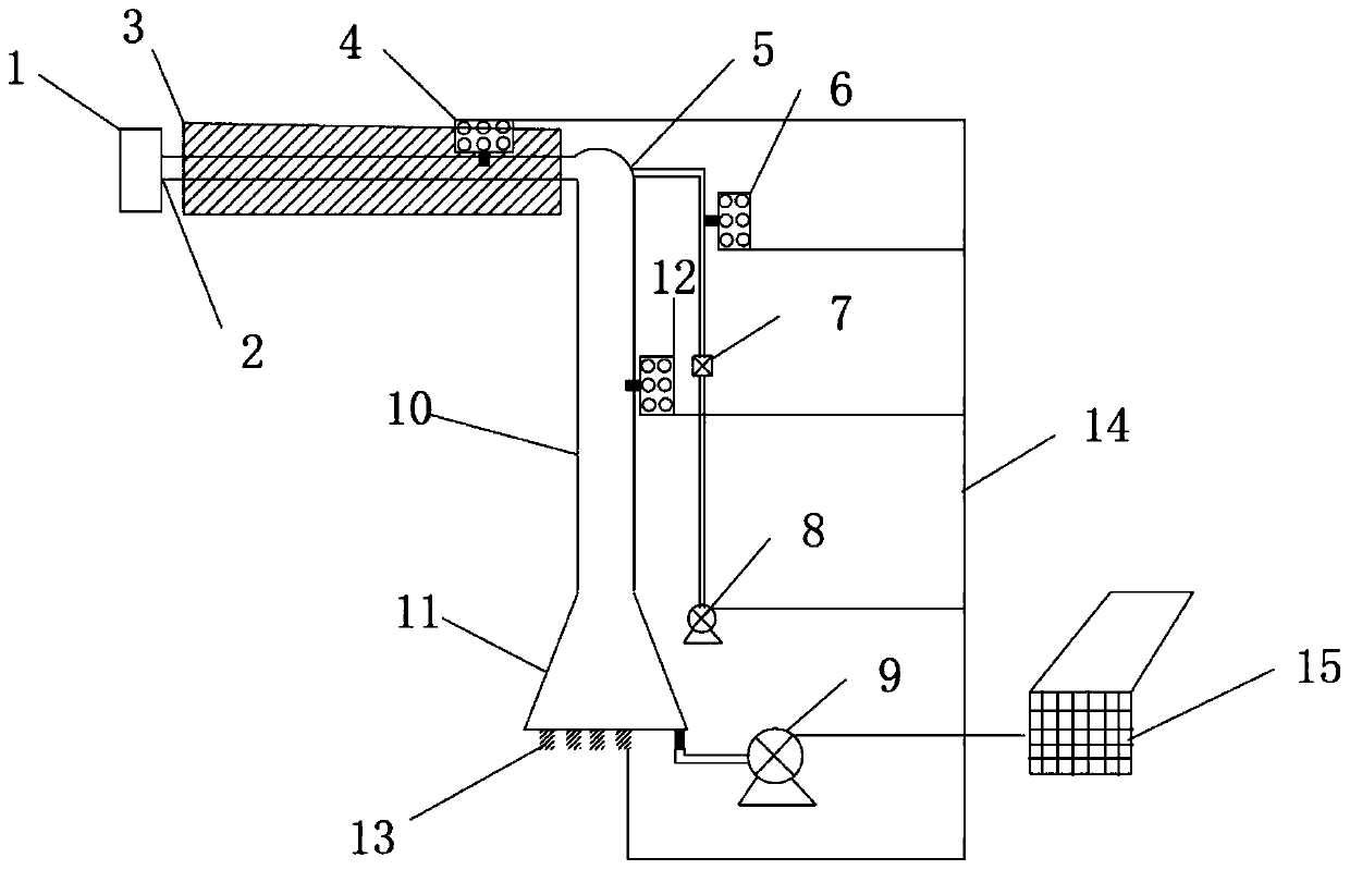
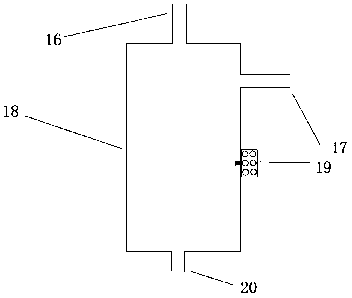
[0031] Such as figure 1 , figure 2 As shown, a flue gas dilution sampling control system includes a flue gas collection pipeline 2, a flue gas mixing chamber 5 and a dilution gas supply device; one end of the flue gas collection pipeline 2 is used to collect the flue gas to be tested, and the flue gas collection pipe The other end of the road 2 is connected to the flue gas mixing chamber 5, the dilution gas supply device is connected to the flue gas mixing chamber 5 through the dilution pipe, the lower end of the flue gas mixing chamber 5 is provided with a dilution chamber 10, and the lower end of the dilution chamber 10 is provided with multiple The sampling interface 13 connected to the monitoring instrument also includes an auxiliary suction pump 9 and a secondary dilution device 18 connected to one of the sampling interfaces 13 through pipelines;

[0032] The l...


PUM


Abstract

The invention discloses a flue gas diluting sampling control system and method. A flue gas collecting pipeline, a flue gas mixing cavity and a diluted gas supply device form a flue gas mixing and diluting system, one end of the flue gas collecting pipeline is used for collecting to-be-detected flue gas, the other end of the flue gas collecting pipeline communicates into the flue gas mixing cavity,the diluted gas supply device communicates into the flue gas mixing cavity through a diluted pipeline, a diluting cavity is formed in the lower end of the flue gas mixing cavity, and the lower end ofthe diluting cavity is provided with a plurality of sampling interfaces for connecting a monitoring instrument. The flue gas diluting sampling control system also comprises an auxiliary suction pumpand a second-stage diluting device connected with one of the sampling interfaces through a pipeline. A controller is used for acquiring the initial concentration of the to-be-detected gas through a first integrated sensor, and the flows of a diluting pump and the auxiliary suction pump are adjusted according to the measuring range of the sampling instrument connected to the lower end of the diluting cavity, so that the purpose of adjusting the gas concentration in the diluting cavity is achieved; and the purpose of automatically controlling the diluting ratio can be achieved according to the preset threshold.

Description

technical field [0001] The invention belongs to a flue gas treatment system, in particular to a flue gas dilution sampling control system and method. Background technique [0002] Atmospheric fine particulate matter (PM 2.5 ) source analysis process, it is very important to understand the chemical composition spectrum of PM2.5 directly emitted by major air pollution sources for the further use of numerical models to obtain a pollution source share rate of PM2.5 that is closer to the actual situation. When collecting biomass fuel boiler flue gas source samples under actual site conditions, due to the limitation of sampling time and industrial production process requirements, it is difficult to collect aerosol source samples with different combustion temperatures, and it is impossible to obtain chemical composition emission factors. Further more accurate assessment of the contribution of biomass boilers to PM2.5 brings great uncertainty. [0003] However, in the prior art, t...

Claims


Application Information

Patent Timeline
Patent Type & Authority Applications(China)
IPC IPC(8): G01N1/38G01N1/22G01N33/00G01D21/02
Inventor 孙健沈振兴李旭祥曹军骥牛馨祎
Owner XI AN JIAOTONG UNIV
Why Eureka
Try Eureka