

Planar phased array-based two-dimensional beam scanning method
A beam scanning, plane phase technology, applied in the field of beam scanning, can solve the problems of unevenness and discrete scanning range, and achieve the effect of continuous scanning, improving diffraction efficiency, and simple and easy-to-understand model.
- Summary
- Abstract
- Description
- Claims
- Application Information
AI Technical Summary
Problems solved by technology
Method used
Image

Examples
Embodiment Construction
[0030] Embodiments of the present invention will be described below in conjunction with the accompanying drawings. However, the following examples are limited to explain the present invention.
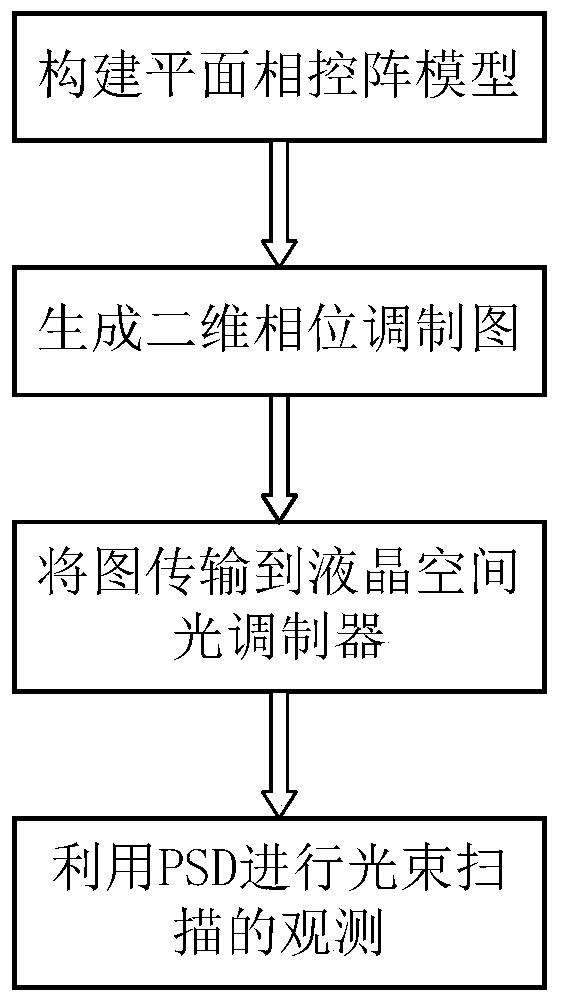
[0031] The present invention is a two-dimensional beam scanning method based on a planar phased array, and the specific steps are as follows:
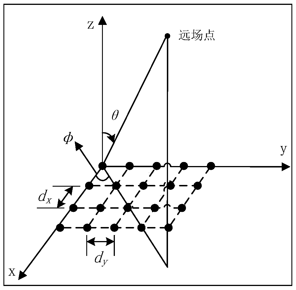
[0032] Step 1. Establish as figure 1 In the planar phased array scanning model shown, θ is the scanning pitch angle, φ is the scanning azimuth angle, N is the number of array elements in the x direction, M is the number of array elements in the y direction, choose N=M=200, and the wavelength of the incident light wave 532.8nm, d x and d y represent the distance between the array elements in the x direction and the y direction respectively, and the average value is half a wavelength. The electric field intensity pattern of a specific point in the far field can be expressed as the product of the pattern in the x direction and the y direction, ...
PUM
 Abstract
Description
Claims
Application Information