Small ultra-wide beam cavity-backed two-layer microstrip antenna and wide-angle scanning array thereof

A microstrip antenna, wide-angle scanning technology, applied in the field of antennas, can solve the problems of increasing the antenna section height, narrowing the antenna beam width, narrowing the antenna beam width, etc., to achieve the effect of compact structure, wide beam width and high performance

Inactive Publication Date: 2019-05-21
XIDIAN UNIV +1
View PDF4 Cites 13 Cited by
  • Summary
  • Abstract
  • Description
  • Claims
  • Application Information

AI Technical Summary

Problems solved by technology

There is a certain distance between the three-dimensional floor and the microstrip patch, which increases the section height of the antenna when used, and this method is not conducive to processing
[0004] To sum up, the problems existing in the prior art are: the height of the antenna is limited in the existing mobile communication, and when the size

Method used


Image

  • Small ultra-wide beam cavity-backed two-layer microstrip antenna and wide-angle scanning array thereof
  • Small ultra-wide beam cavity-backed two-layer microstrip antenna and wide-angle scanning array thereof
  • Small ultra-wide beam cavity-backed two-layer microstrip antenna and wide-angle scanning array thereof

Examples


Embodiment Construction

[0038] In order to make the object, technical solution and advantages of the present invention more clear, the present invention will be further described in detail below in conjunction with the examples. It should be understood that the specific embodiments described here are only used to explain the present invention, not to limit the present invention.

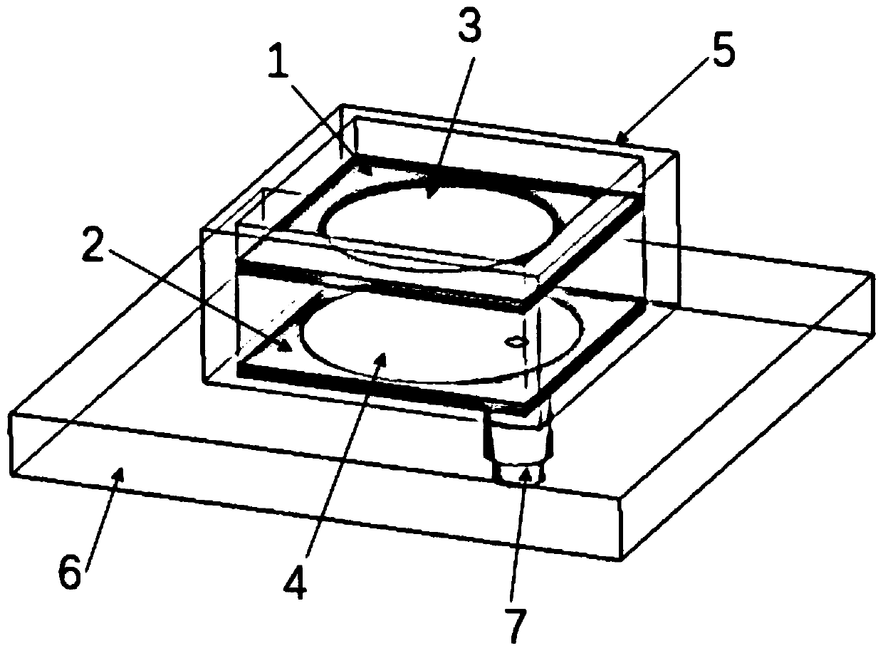
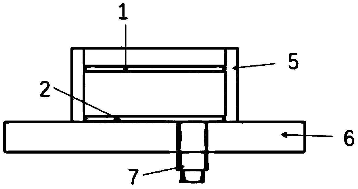
[0039] In existing mobile communications, the height of the antenna is limited, and when the size is limited, the beam width of the antenna is relatively narrow. The thickness of the antenna of the invention is less than 0.16λ, the impedance bandwidth of the antenna reaches more than 14%, and the half-power beam width of the E plane can reach 190°; the linear polarization characteristic is good, and the beam width is relatively wide.

[0040] The application principle of the present invention will be described in detail below in conjunction with the accompanying drawings.

[0041] Such as figure 1 and figure 2 As shown,...


PUM


Abstract

The invention belongs to the field of antenna technology, and discloses a small ultra-wide beam cavity-backed two-layer microstrip antenna and a wide-angle scanning array thereof. A parasitic dielectric substrate is located on the upper layer of the small ultra-wide beam cavity-backed two-layer microstrip antenna; a metal back cavity is located at the lowermost layer of the small ultra-wide beam cavity-backed two-layer microstrip antenna; and the metal back cavity is a metal cavity in a rectangular form, which closely surrounds a radiation medium substrate and the parasitic dielectric substrate. The invention adopts single point feed to radiate linearly polarized electromagnetic wave. Since the circular microstrip patch is of a small size and a compact structure, the side length of the whole antenna is less than 0.46[lambda]; the antenna thickness is less than 0.16[lambda]; the antenna impedance bandwidth is more than 14%; and the E-plane half-power beam width can reach 190 degrees. For a multi-element linear array assembled by the antenna, the space between elements is less than 0.44[lambda], and the gain is only reduced by 3dB in the scanning range of the E-plane +/- 82 degrees.The invention may also constitute an operating mode of dual-linear polarization and circular polarization.

Description

technical field [0001] The invention belongs to the technical field of antennas, in particular to a small ultra-wide beam cavity-backed double-layer microstrip antenna and a wide-angle scanning array thereof. Background technique [0002] At present, the existing technologies commonly used in the industry are as follows: in the development process of antennas, there are increasingly higher requirements for the performance of high directivity and fast variable beams. Before the appearance of the phased array antenna, the traditional mechanical scanning antenna can only realize the scanning of the antenna through mechanical rotation, and the phased array antenna has been widely used since its appearance because of its high-speed and accurate beam scanning. Generally speaking, the limit scanning angle of the phased array antenna is about ±60°. Whether it is a radar system or an electronic countermeasure system, in order to expand its target search range, improve its survivabil...

Claims


Application Information

Patent Timeline
IPC IPC(8): H01Q1/36H01Q1/50H01Q1/28H01Q1/32H01Q1/34
Inventor 李政佑陈曦邢裕昕郭浩傅光
Owner XIDIAN UNIV
Why Eureka
Try Eureka