
Low-grade heat energy driven electrode liquid self-circulating hydrogen production method

A self-circulating, electrode liquid technology, applied in the direction of electrolysis process, electrolysis components, regenerative fuel cells, etc., can solve the problems of large energy consumption, large energy conversion loss, high electrode potential, etc.

Active Publication Date: 2019-05-28
DALIAN UNIV OF TECH
View PDF2 Cites 12 Cited by
  • Summary
  • Abstract
  • Description
  • Claims
  • Application Information

AI Technical Summary

Problems solved by technology

[0004] From the perspective of hydrogen production, even if the above-mentioned heat-to-electricity conversion technology based on the power conversion positive cycle system develops mature in the future, there are still some shortcomings in the direct use of the high-grade electric energy generated by it to electrolyze water to produce hydrogen, such as high electrode potential and energy consumption. Large amount, high energy conversion loss, etc., and usually requires the temperature of the driving heat source to be above 150°C

Method used


Image

  • Low-grade heat energy driven electrode liquid self-circulating hydrogen production method
  • Low-grade heat energy driven electrode liquid self-circulating hydrogen production method

Examples


Embodiment 1

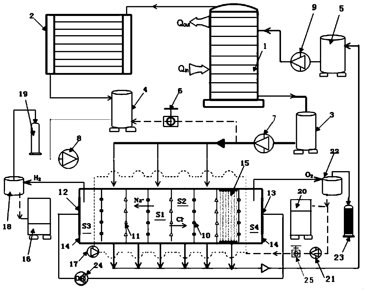
[0030] Example 1: figure 1 It shows a working flow of a self-circulating (no plug-in) hydrogen production method driven by low-grade thermal energy based on the principle of reverse electrodialysis. acidic NaHSO 4 The aqueous solution is the electrode circulation liquid. Include the following steps:

[0031] In the first step, the low-grade thermal energy stream (such as low-temperature heat transfer oil with a temperature of 120-130°C) enters the generator 1 from the inlet of the driving heat source at the bottom left of the generator 1, and the working solution (such as chlorinated Sodium aqueous solution), after releasing heat and cooling down to about 60°C, leave the generator 1 from the outlet of the driving heat source on the upper left of the generator 1. After the waste liquid in the generator 1 is heated by the low-grade thermal energy stream, part of the solvent and a very small amount of solute will evaporate, and escape from the top of the generator in gaseous f...

Embodiment 2

[0041] Example 2: It is also a low-grade thermal energy-driven electrode solution circulation (no plug-in) hydrogen production method based on the principle of reverse electrodialysis, and its working principle is still the same as figure 1 shown. Compared with the specific embodiment 1, what is added in the reverse electrodialysis cell stack in the specific embodiment 2 is an alkaline electrode solution, such as NaOH aqueous solution, etc., between the hydrogen-producing anolyte chamber S3 and the oxygen-producing anolyte chamber S4 Circular flow. The first step and the second step in the working process of the specific embodiment 2 are completely the same as those of the aforementioned specific embodiment 1, and will not be repeated here. The difference lies in the third step.

[0042] In the third step, in terms of hardware conditions, Embodiment 2 is also the same as Embodiment 1, so there is no need to describe it redundantly. The difference lies in the chemical reactio...

Embodiment 3

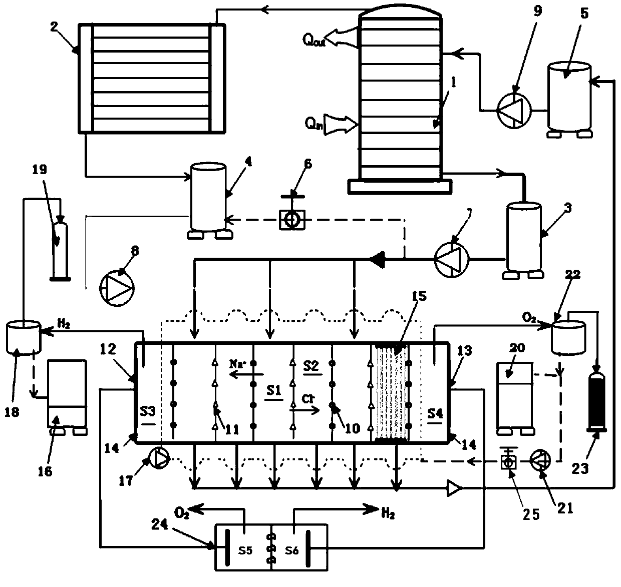
[0045] Example 3: figure 2 Shown is a low-grade thermal energy-driven electrode liquid self-circulation (with plug-in) hydrogen production method work flow based on the principle of reverse electrodialysis.

[0046] On the basis of specific embodiment 1 or specific embodiment 2, if the number of anion and cation exchange membranes (which can significantly improve the output voltage of the reverse electrodialysis stack) is increased to more than 30 pairs, and the variable load 24 is selected as an external electrolyzer, so reverse electrodialysis hydrogen production-electrolysis water method can simultaneously produce hydrogen and oxygen, then more hydrogen and oxygen can be produced on the original basis. figure 2 shown.

[0047] The principles of the specific embodiment 1 and the specific embodiment 2 are basically similar, and the same parts will not be repeated. In addition to increasing the number of ion exchange membranes, the key difference is that the specific embod...


PUM


Abstract

The invention discloses a low-grade heat energy driven electrode liquid self-circulating hydrogen production method, and belongs to the technical field of new energy. Low-grade heat energy serves as driving force, and continuous hydrogen production is achieved through the concentration change of a working solution. The low-grade heat energy driven electrode liquid self-circulating hydrogen production method comprises the steps: firstly, the low-grade heat energy is converted into chemical potential energy of the working solution through a low-temperature multi-effect distillation method; thenthe chemical potential energy is converted into the potential difference between two electrodes of a cell stack based on the reverse electrodialysis principle; and then hydrogen and oxygen are produced through a reduction reaction or an oxidation reaction occurring on the hydrogen production electrode and the oxygen production electrode in the same electrode liquid. The waste solution losing partof the chemical potential energy is recycled after flowing out from the cell stack, and then regenerated under driving of the low-grade heat energy; the electrode liquid is self-circulated between a hydrogen production electrode liquid cavity and an oxygen production electrode liquid cavity in the two ends of the cell stack; the low-grade heat energy can be continuously, efficiently and steadily converted to be utilized; a hydrogen production system does not need to operate at the high temperature and high pressure, mechanical moving parts are few, and capacity configuration is flexible; and the single-type electrode liquid is adopted and is in an electrolyte closed cycle, and long-time operation can be achieved only by supplying deionized water.

Description

technical field [0001] The invention belongs to the technical field of new energy, and relates to a method for realizing continuous hydrogen production with low-grade thermal energy as the driving force and by means of concentration changes of working solutions. Background technique [0002] Hydrogen energy is considered to be a new energy source with great development potential due to its advantages such as high energy density, environmentally friendly combustion products, abundant sources (water) and reserves, and a wide range of applications. At present, the common hydrogen production methods mainly include hydrogen production by electrolysis of water, hydrogen production by gasification of coal, catalytic conversion of heavy oil and natural gas water vapor production, etc., but the energy consumed by these methods is greater than the energy produced by them, and some methods are It will increase carbon emissions and exacerbate air pollution. If the method of hydrogen pr...

Claims


Application Information

Patent Timeline
IPC IPC(8): C25B1/04C25B9/04H01M8/18
CPCY02E60/36Y02E60/50
Inventor 吴曦徐士鸣
Owner DALIAN UNIV OF TECH
Learn More