A water outlet pipe forming process
A molding process and water outlet technology, applied in the field of sanitary ware, can solve problems such as production
- Summary
- Abstract
- Description
- Claims
- Application Information
AI Technical Summary
Problems solved by technology
Method used
Image
Examples
no. 1 example
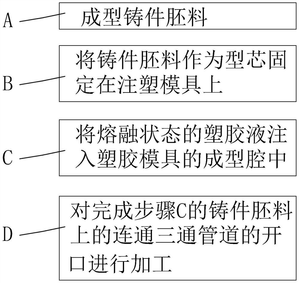
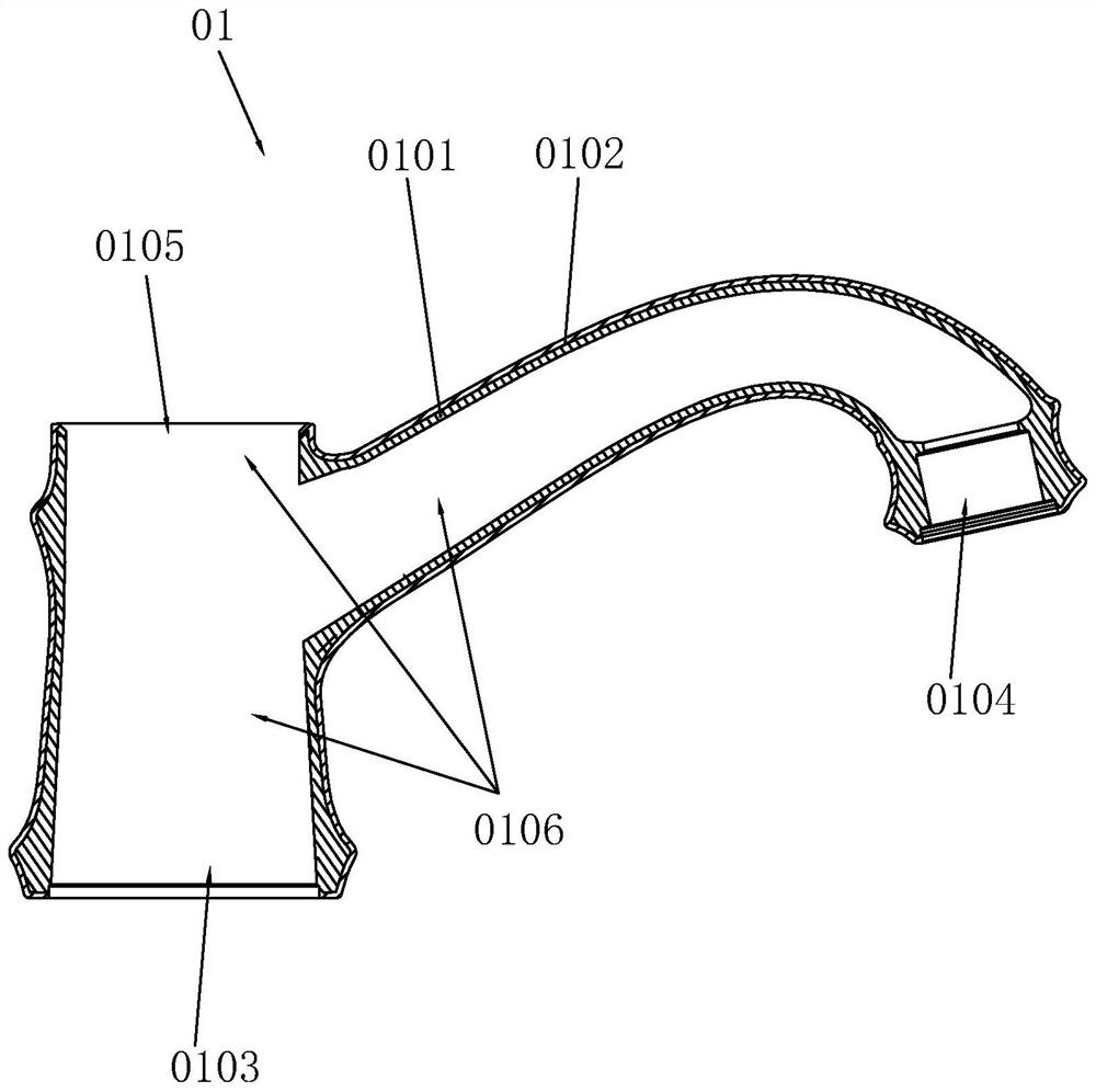
[0037] refer to figure 1 and combine image 3 , The invention provides a water outlet pipe of a faucet and a manufacturing process thereof. The water outlet pipe in the present invention includes a base body with an inner layer, and a composite layer of plastic material covering the outside of the base body. The metal matrix composite material layer covers the base body by injection molding. The main body of the base in this embodiment is zinc alloy, which has a low melting point and good fluidity, and has relatively low manufacturing process requirements, that is, low manufacturing cost. The plastic material composite layer is a plastic material composite layer prepared by mixing polymer plastic materials, metal powder, fibers, additives and graphene. Wherein, the selected proportions of the components of the plastic shell 0102 are: 30%-60% of polymer plastic materials, 10%-20% of fibers, 0.8%-3% of additives, 0.5%-5% of graphene %, the balance of metal powder. In this e...
no. 2 example
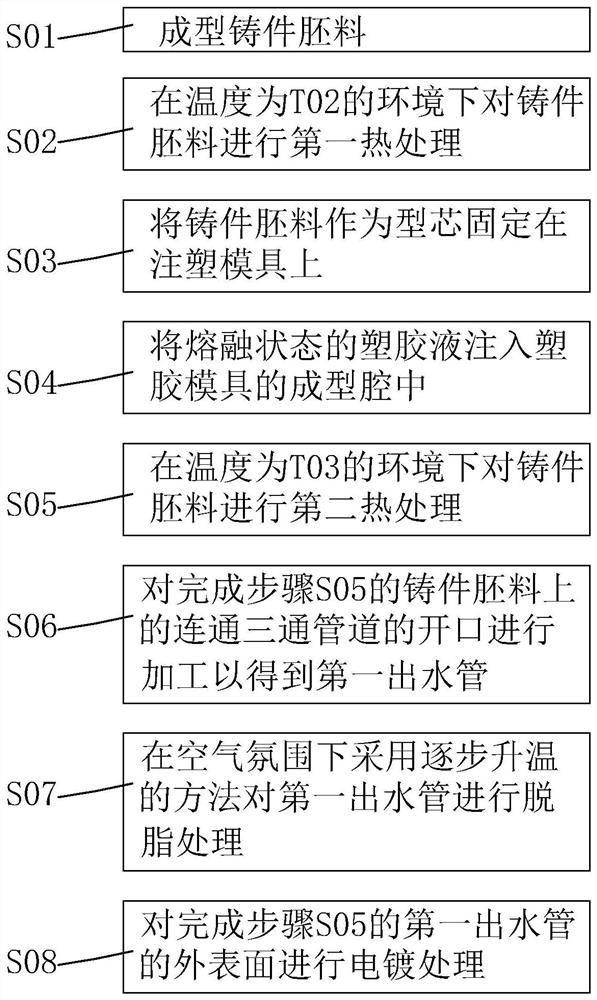
[0056] combine Figure 3 to Figure 11 , the above-mentioned first embodiment has provided a process that can produce qualified water outlet pipe components. In the above step D, when the first opening 0103, the second opening 0104 and the third opening 0105 on the water outlet pipe are processed, the processing eccentricity often occurs, and the eccentric positions of the holes processed by different batches of products are different. It is different (for example: one side of the hole is not processed enough to cause black skin, and the other side is processed too much, causing the wall thickness of the other side of the casting blank 0101 to be thinner). After verification, the inventor found that the reason for this is that every time during production, in step B, when the casting blank 0101 formed in step A is fixed in the molding cavity of the injection mold 06, its fixed angle will be Changes occur, and the changes lead to changes in the machining allowance at the same p...
no. 3 example
[0068] The present application further provides a third embodiment, which achieves a technical effect similar to that of the second embodiment. combine Figure 5 , Figure 6 as well as Figure 8 Specifically, the first limiting mechanism 07 includes a first limiting member used to limit the position of the first opening 0103 in the first direction, and cooperates with the first limiting member to define the position of the second opening 0104 in the first direction. The second limiting member is a desired distance L1 away from the first opening 0103 in the direction. The first limiting member includes a first end surface 0108B located at the first opening 0103 on the casting blank 0101, a first positioning portion 0302 configured on the injection mold 06 to abut against the first end surface 0108B, and a second limiting member It includes a second end surface 0109B located at the second opening 0104 on the casting blank 0101, a second positioning portion 0402 configured on ...
PUM
| Property | Measurement | Unit |
|---|---|---|
| thickness | aaaaa | aaaaa |
| thickness | aaaaa | aaaaa |
| thickness | aaaaa | aaaaa |
Abstract
Description
Claims
Application Information
 - R&D
- Intellectual Property
- Life Sciences
- Materials
- Tech Scout
- Unparalleled Data Quality
- Higher Quality Content
- 60% Fewer Hallucinations
Browse by: Latest US Patents, China's latest patents, Technical Efficacy Thesaurus, Application Domain, Technology Topic, Popular Technical Reports.
© 2025 PatSnap. All rights reserved.Legal|Privacy policy|Modern Slavery Act Transparency Statement|Sitemap|About US| Contact US: help@patsnap.com


