Composite material thermal vibration fatigue test device and method based on reverse resonance

A composite material and fatigue test technology, which is applied in the direction of measuring device, vibration test, machine/structural component test, etc., can solve the problems of thermal dynamic fatigue performance research of composite materials, surface oxidation of cooling objects, larger temperature difference of samples, etc. , to improve test efficiency, save energy, and simplify equipment

Inactive Publication Date: 2019-06-04
NORTHEASTERN UNIV
View PDF16 Cites 3 Cited by
  • Summary
  • Abstract
  • Description
  • Claims
  • Application Information

AI Technical Summary

Problems solved by technology

For example, patents CN 105758758 A, CN107917797 A, and CN 207197971 U all use water cooling as the cooling method. The cooling speed of the water cooling method is fast, but it is not easy to control and it is easy to oxidize the surface of the cooling object, and the water cooling will cause a larger temperature difference inside the sample. , may lead to greater thermal stress, which will make the conditions of the thermal fatigue test different from the actual ones. Therefore, water cooling is not suitable for thermal fatigue analysis of composite materials, while air cooling uses air as the cooling medium, which is energy-saving, environmentally friendly, space-saving, stable and reliable. Features, which have broad prospects in the field of thermal fatigue testing, suitable for thermal dynamic fatigue testing of composite materials
[0006] Common fatigue testing machines include h

Method used


Image

  • Composite material thermal vibration fatigue test device and method based on reverse resonance
  • Composite material thermal vibration fatigue test device and method based on reverse resonance
  • Composite material thermal vibration fatigue test device and method based on reverse resonance

Examples


Embodiment Construction

[0043] It should be noted that all directional indications (such as up, down, left, right, front, back...) in the embodiments of the present invention are only used to explain the relationship between the components in a certain posture (as shown in the accompanying drawings). Relative positional relationship, movement conditions, etc., if the specific posture changes, the directional indication will also change accordingly.

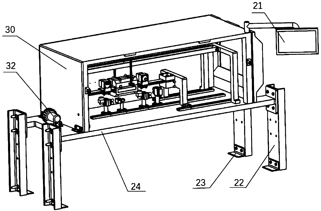
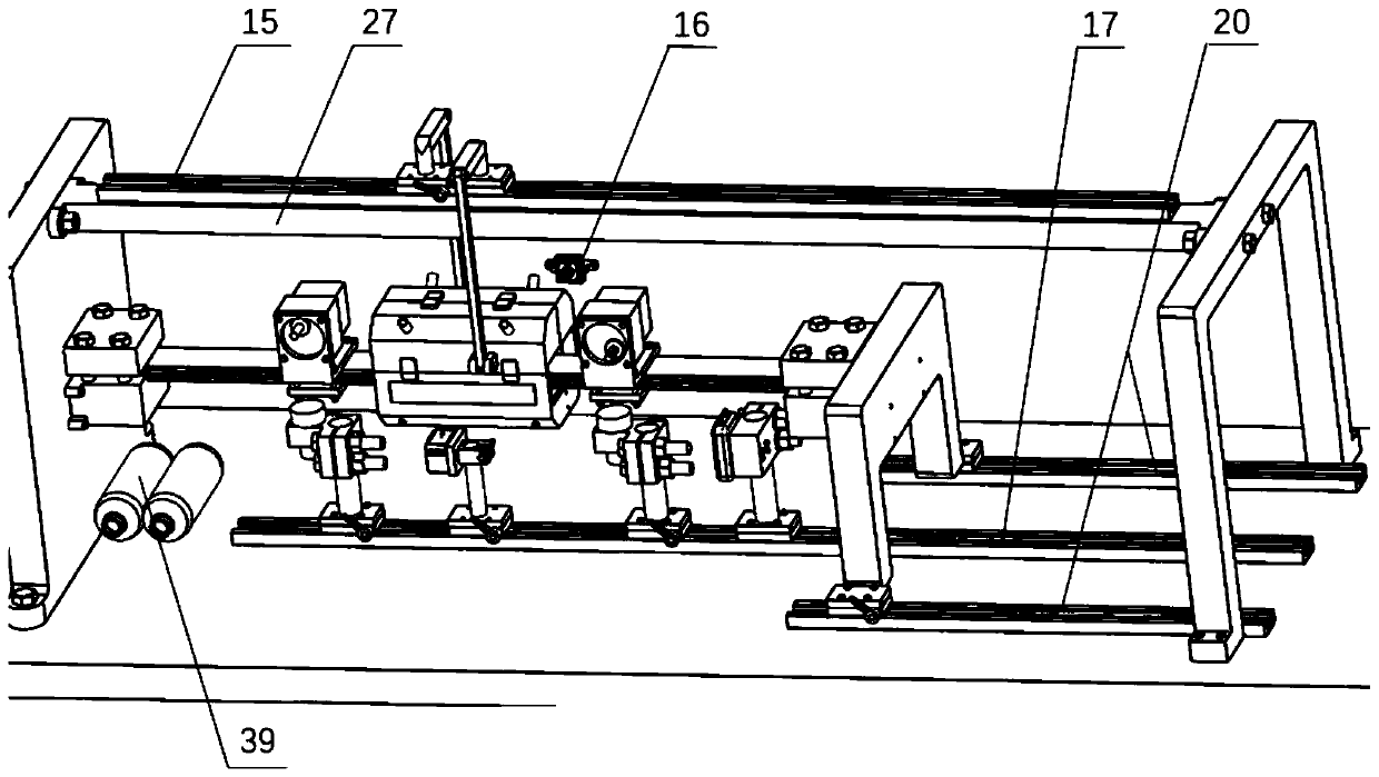
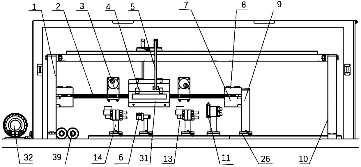
[0044] Such as Figure 1 to Figure 9 As shown, the present invention provides a thermal vibration fatigue test device for composite materials based on reverse resonance, including a double cantilever beam vibration test system, a thermal environment simulation system, an electronic acquisition system, and a measurement and control system;

[0045] The double cantilever beam vibration test system includes two cantilever vibrating beams 2, an eccentric motor 3 and a base plate 24, the left side fixed plate 1 is fixedly installed on the left side of the top...


PUM


Abstract

A composite material thermal vibration fatigue test device and method based on a reverse resonance are disclosed. The test device comprises a double-cantilever-beam vibration test system, a thermal environment simulation system, an electronic acquisition system, and a measurement and control system; an eccentric motor is used to drive a beam to be tested to vibrate. Compared with a vibration exciter, the device of the invention has a small size and less energy consumption, and is convenient to carry. The reverse resonance of a double-cantilever vibration beam is used to drive the beam to be tested to vibrate, test efficiency is improved, energy is saved, and an amplitude range of the beam to be tested is widened compared with existing test equipment. A variety of precision instruments areused to measure and analyze a fatigue characteristic of a material to be tested from optical, acoustic, time domain waveforms and other aspects, and high test accuracy is achieved. A thermal environment where the composite material is located can be simulated, and the fatigue characteristic of the composite material at different temperatures can be tested. The device of the invention is simple, components adopt a detachable design, disassembling is convenient, the portability is good, and the operation is easy.

Description

technical field [0001] The invention belongs to the technical field of composite material structure fatigue testing, and in particular relates to a thermal vibration fatigue testing device and method for composite materials based on reverse resonance. Background technique [0002] As we all know, thermal fatigue refers to the uneven temperature distribution of materials in the environment of temperature changes. Due to the different expansion degrees, the deformation of different parts is restrained, and cyclic thermal stress or thermal strain is generated inside the material, resulting in crack initiation and propagation. , the eventual phenomenon of material failure. With the rapid development of various fields, the performance enhancement indicators of various materials are increasing day by day, and the damage caused by thermal fatigue is increasing day by day. Composite components are often damaged or even destroyed due to stress and environmental factors (especially t...

Claims


Application Information

Patent Timeline
IPC IPC(8): G01M7/02
CPCG01M7/02G01N29/04
Inventor 任朝晖黄浩诚戴哲鑫王俊石有泰吴腾飞王文煜李晖
Owner NORTHEASTERN UNIV
Why Eureka
Try Eureka