
Power level simulation control method and device of three-phase alternating current motor

A motor simulation and three-phase AC technology, applied in simulators, general control systems, control/regulation systems, etc., can solve problems such as simulation errors and current feedback errors, and avoid FPGA programming and expensive high-performance computing chips Effect

Active Publication Date: 2019-06-04
TSINGHUA UNIV
View PDF27 Cites 9 Cited by
  • Summary
  • Abstract
  • Description
  • Claims
  • Application Information

AI Technical Summary

Problems solved by technology

Since the current closed-loop control of the motor simulator inevitably has a delay, compared with the actual current, the current feedback obtained by the motor driver has a certain error, which also brings simulation errors

Method used


Image

  • Power level simulation control method and device of three-phase alternating current motor
  • Power level simulation control method and device of three-phase alternating current motor
  • Power level simulation control method and device of three-phase alternating current motor

Examples


Embodiment 1

[0096] Embodiment 1 Squirrel-cage asynchronous motor:

[0097] (3) formula becomes:

[0098]

[0099] where ψ rd is the rotor d-axis flux linkage; L m , L s , L r are the stator-rotor mutual inductance, stator self-inductance and rotor self-inductance respectively; σ is the flux leakage coefficient, and σ=1-L m 2 / (L s L r ). ψ rd It can be obtained by the flux observer. For example, take the following flux observer based on the current model:

[0100]

[0101] ψ in the formula rα with ψ rβ is the component of the rotor flux linkage along the α-axis and β-axis in the two-phase stationary coordinate system (that is, the αβ coordinate system), T r is the rotor time constant, ω e is the rotor electrical angular velocity. Observe that ψ rα with ψ rβ Afterwards, ψ is calculated by rd with θ:

[0102]

[0103] Meanwhile (4) becomes:

[0104]

[0105] With the help of (5), the rotor speed can be calculated.

Embodiment 2

[0106] Embodiment 2 permanent magnet synchronous motor:

[0107] (3) formula becomes:

[0108]

[0109] where ψ f is the flux linkage generated by the permanent magnet; L d , L q are the d-axis inductance and q-axis inductance of the motor, respectively.

[0110] (4) becomes:

[0111] T e =1.5n p [(L d -L q )i sd i sq + i sq ψ f ] (11)

[0112] With the help of (5), the rotor speed can be calculated, and the θ required for dq transformation can be obtained by integrating the speed.

Embodiment 3

[0113] Embodiment 3 Electric excitation synchronous motor:

[0114] (3) formula becomes:

[0115]

[0116] In the formula, L d , L q are the d-axis inductance and q-axis inductance of the motor, m af is the exciting inductance, i f is the excitation current.

[0117] (4) becomes

[0118] T e =1.5n p [(L d -L q )i sd i sq + i sq m af i f ] (13)

[0119] With the help of (5), the rotor speed can be calculated, and the θ required for dq transformation can be obtained by integrating the speed.

[0120] Compared with the expression in the embodiment of the permanent magnet synchronous motor, the expression in the embodiment of the electric excitation synchronous motor is only the rotor d-axis flux linkage ψ f change to m af i f , that is, the rotor flux linkage produced by the permanent magnets is transformed into that produced by the excitation current.

[0121] It is important to note that since there is no limit to L d , L q The value of , this simulation...


PUM


Abstract

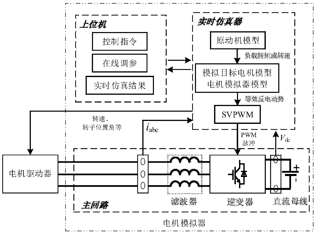
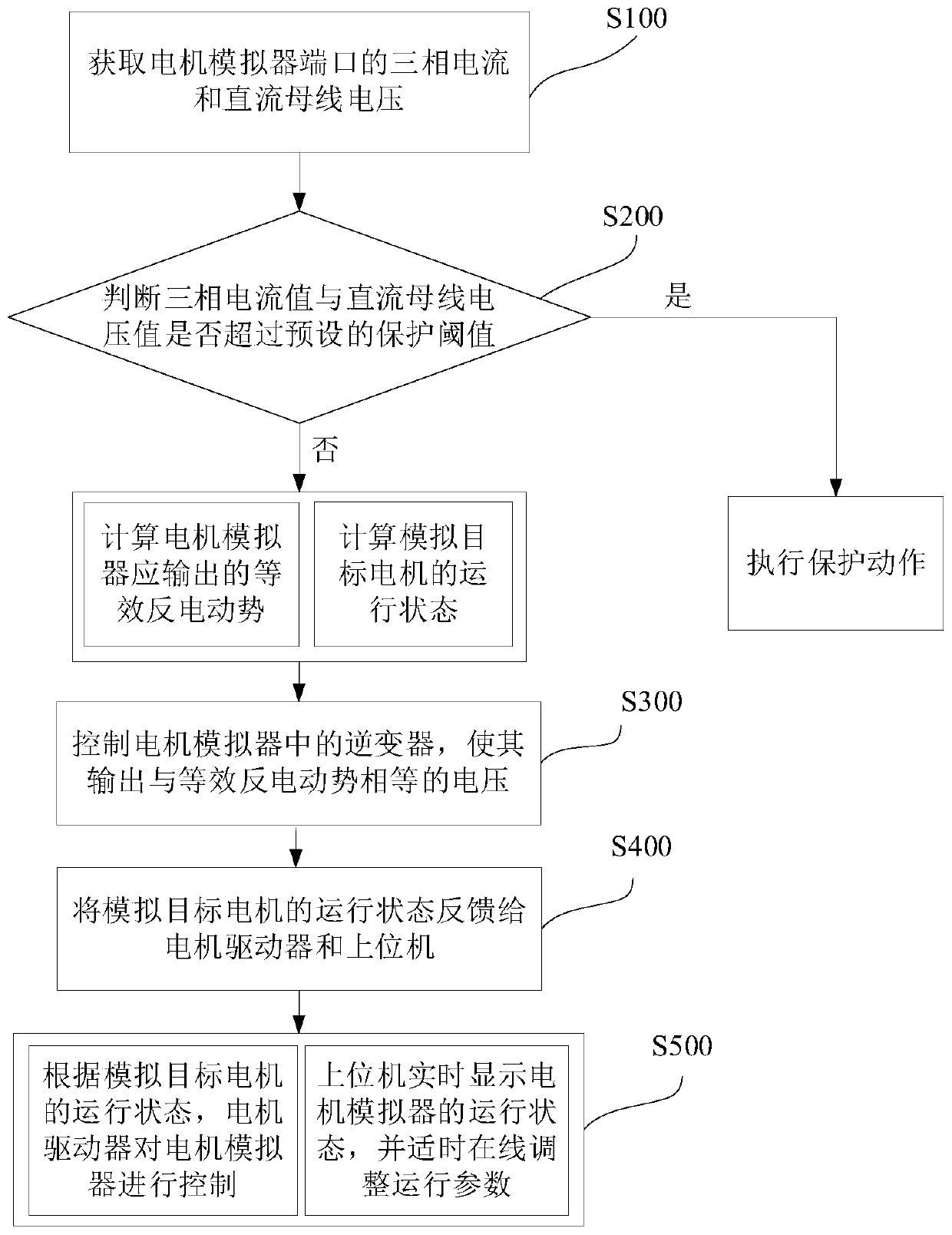
A power level simulation control method and device of a three-phase alternating current motor are disclosed. The method is characterized by acquiring a three-phase current of a main loop of a motor simulator and a direct current bus voltage through sampling, and determining whether a three-phase current value and a direct current bus voltage value exceed a preset protection threshold; if the three-phase current value and the direct current bus voltage value exceed the preset protection threshold, carrying out protection motion; if the three-phase current value and the direct current bus voltage value do not exceed the preset protection threshold, calculating an equivalent counter electromotive force output by a motor simulator according to a simulated target motor and a mathematical modelof the motor simulator so as to control the motor simulator so that voltage and current characteristics of a three-phase port are not different from those of the simulated target motor. Simultaneously, a simulated target motor operating state calculated according to the mathematical model is fed back to a motor driver so as to complete a motor control process. In the invention, a three-phase portcurrent value of the motor simulator and the direct current bus voltage value only need to be sampled so as to avoid the sampling of a three-phase port voltage containing a large number of higher harmonics; and simultaneously, the motor simulator does not need to carry out closed-loop control on the three-phase port current, and system stability is improved.

Description

technical field [0001] The invention relates to the technical field of motor simulation, in particular to a power level simulation control method and device for a three-phase AC motor. Background technique [0002] In the process of developing and debugging the motor driver (generally a frequency converter based on power electronic technology), in order to test its control performance on the motor under various working conditions, a power electronic converter can be used to simulate the port voltage and current of the motor to be tested characteristics, instead of the motor to be tested (hereinafter referred to as "simulation target motor") connected to the motor driver. Compared with the traditional AC drive test platform, this power-level motor simulation method has strong versatility, energy saving and environmental protection, and improves the safety of the test. In the existing power-level motor simulation method, it is necessary to sample the voltage of the three-phas...

Claims


Application Information

Patent Timeline
Patent Type & Authority Applications(China)
IPC IPC(8): G05B17/02
Inventor 肖曦邹晓敏宋宇洋
Owner TSINGHUA UNIV
Learn More